Broadcom ACPL-32JT Manual do utilizador - Página 2
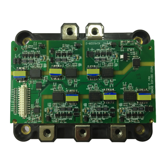
Procurar online ou descarregar pdf Manual do utilizador para Placa-mãe Broadcom ACPL-32JT. Broadcom ACPL-32JT 16 páginas. Evaluation driver board for fuji m652 6-in-1 igbt
ACPL-32JT, ACPL-C87AT
Board Operation
Power Supply
The board accepts 8V to 18V applied across DC12 to GND1. The
nominal voltage is 12V.
PWM Inputs
There are six Pulse Width Modulation (PWM) inputs for driving
the IGBT module: PWMLW, PWMHW, PWMLV, PWMHV, PWMLU,
PWMHU.
0V: Input Low
5V: Input High (max 5.5V)
Signals are referenced to GND1.
The input LEDs of the ACPL-32JT gate drivers are driven by an
on-board current buffer.
Desat Fault Feedback
There are six Desat Fault feedback outputs, one for each IGBT:
FLU, FHU, FLV, FHV, FLW, FHW.
When fault on gate driver secondary side is detected, Fault
feedback is pulled Low.
Low: Desat Fault Detected
High (5V): No Fault
UVLO Feedback
There are six Under-Voltage Lock Out (UVLO) feedback outputs,
one for each IGBT: ULU, UHU, ULV, UHV, ULW, UHW.
When undervoltage on gate driver secondary side is detected,
UVLO feedback is pulled Low.
Low: Undervoltage Detected
High (5V): Voltage Normal
Board Design
Gate Driving
Figure 2 Gate Driving
The Gate Driver output is connected to a push-pull buffer to
drive the IGBT gate.
The strength of the turn-on and turn-off is controlled by Ron
and Roff respectively (R23 and R24 in
Soft Shutdown
Figure 3 Soft Shutdown
Broadcom
- 2 -
User Guide
Figure
2).