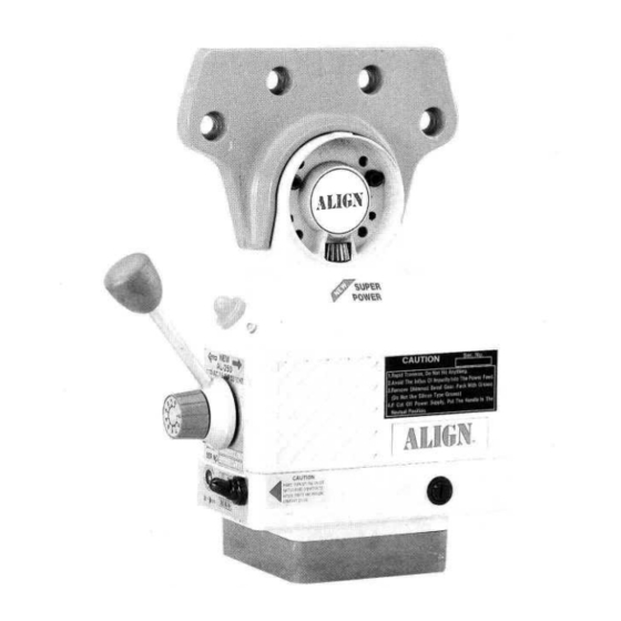
Align AL-250 Manual do operador - Página 10
Procurar online ou descarregar pdf Manual do operador para Ferramenta eléctrica Align AL-250. Align AL-250 10 páginas. Power table feed

STEP
5
HOW TO
INSTALL KNEE LIFT
FEED
STEP
1
Nol€: Remove the bevel gear
(No
6)
,(er
Slep
(4) is
O K
,
lhtr
indall
key, rsplac€
gear, install dial,
dd
tighten dial nul
(Add a few shims il
dial
is
grinding the
gear
)
lmponanl:
Pack with
gr@
b€fore
installing
the
gear
(Do
not
us
siliconfyp€
grea*
)
,
n
STEP 6
Note:
lnstall @ Check Clutch Against
@
Bevel Goar Then Drivl Through One
Hole Ot smm
Dia
.
Th€n
Orive
Spring
Pin
lmpodanl: Be sure you have ,ollowed
each
sl€p
care,ullyild
cor@tly b€lore
installing the spring pins
Suggeslions:
lnstall hand crank rolale
in
Note:
Remove hand
crank, dial, dial s@ket,
tEaring
llange
and
Etc
STEP 2
u
prop€r
shiming
dd
lhatthere
is no binding action
o-2
Nole:
lnslall O
extension shafl
lmpodant:
(1) Shatt
end musl be against
in-
ner ring
ol
b€ring
(2) lnner
shaft
is16or
t8
thr@ded unc
STEP
7
I
o)
I
DI
D'ta
Dl3
Nole: lnstall spring
(12),
handcrank (already
ingalled),
then tighten
w6her
(13),
ild
$rew
(14)
lmponenl:
For
opdataonal
salety,
pl6e*
lubriml€this
pad and inslall
6
per
instruclios
STEP 3
I
Note: Tighten O
to
llange then tighten
@
lo
knee foed on the tlange
lmponant:
For
angular
Positioning
FIT
FUNGE
G
TABLE
v2
STANDARD ACCESSORIES FOR KNEE
LIFT
FEED
t>5
STEP 4
NO
DESCRIPTION
NO,
DESCRIPTION
D-1
o-2
D-3
D-4
D-6
o-7
D-8
EXTENSION
SHAFT
STANO
BEARING
PO\IJER
FEED
BOOY
scREws
BEVEL
GEAR
SHIMS
SHIMS
D-9
0-10
D,1'l
D-12
D-1
3
D-14
D-l5
D-16
KEY
CLUTCH
PIN
SPRING
WASHEF
FIXED SCREW
STOP BLOCK
T.WAY TRACK
t
Nole:
lnslall
@
gear
O
key not
ln
lmponant: Use hend
to
push
& turn
bevel
gaar
lo
check
backlash
(1) lt
necesstry add
a
lew shims
@ to
oblain prop€r
backlashr Or
(2)
modity
l€ding
odg€ ol gear lo
oF
tain proper back
l8h
Th€n repack
gsar
with
groa$
Boplace gear
then push and
lurn
lo check for
backlsh
_:
