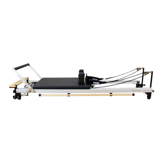
Align-Pilates C Series Instruções de montagem e manual do utilizador - Página 3
Procurar online ou descarregar pdf Instruções de montagem e manual do utilizador para Equipamento de fitness Align-Pilates C Series. Align-Pilates C Series 12 páginas. Reformer

2. Assembling the Foot Bar
a) Carefully cut off the cable ties holding the foot bar in the folded position.
b) With the aid of another person lift up the standing platform end of the reformer and
swing the foot bar out from under the machine.
c) Cut off the cable ties holding the chrome Gear bar (#26 - see exploded
diagram on page 10) and position it in the 2nd slot away from the end of the reformer.
d) Now bolt the Foot bar Selector bar to the chrome Gear bar from the outside using the
M8 20mm bolt (#103) . Now repeat on the other side, but do not fully tighten. See
Fig. 1.
e) Now insert the M8 x 15mm dome headed bolt (#92) from the inside and fully tighten.
Repeat on the other side. See Fig. 2
f) Now fully tighten all four bolts
Note: at this point if you have only ordered the C2–Pro RC, without the extension legs or
freestanding leg attachments please jump to section 3 in the manual.
3. Attaching the Leg Extensions* (optional extra)
If you bought the optional leg height extensions now is a good time to attach
them. We recommend you get a pair of stable trestles to put the reformer on to enable easy fitting of the legs.
Ensuring the trestles have something soft on them to avoid scratching the frame, lift the reformer out of the box and
place it on to the trestles, so that one trestle is underneath the point where the foot bar attaches to the runner and
the other is near the rope riser end.
Remove the wheels at the foot end of the reformer, placing all nuts, bolts and washers to one side. Store the parts in
the order you removed them and then reinstall the wheels on to the higher legs. Remove all four of the black
adjustable screw in feet by unscrewing them completely out and then screw these completely in to the C2-Pro leg
extensions.
Using the allen bolts and a 6mm Allen key, screw in the 5 bolts per leg and hand tighten. Be careful not to cross
thread the bolts. Once all the bolts are in, tighten fully with the Allen key. After removing your trestles or other eleva-
tion device, put your reformer down where you intend to use it. Then use a spirit level to check the reformer is level
and stable. Adjust the level of the reformer by turning the rubber feet in or out. The parts list and exploded diagram is
shown in Fig. 3 for your reference.
4. Free Standing Legs* (optional extra)
The C2-Pro RC model has the ability to free stand with the addi-
tion a pair of freestanding legs (optional extra), shown in Fig.4,
which bolt on to the frame. When standing the reformer always
make sure the spring bar is in the position closest to the stand-
ing platform before lifting. To install the legs simply remove the 4
bolts (part #143), position the leg bracket so that the leg can fold
inwards, then thread the bolts back through the frame and leg and
hand tighten. When all 4 bolts are in tighten fully with a 6mm allen
key. To use the legs, remove the safety pin from its storage location,
then stand the reformer, once vertical open both the legs 90
degrees with your foot and let the reformer free stand. Now reinsert the safety pin to lock the legs open. To lower
remove the safety pin, then whilst supporting the reformer, take the pressure off the legs and fold them in with your foot
then lower the reformer carefully down.
*Both the leg extensions & freestanding legs packages include a new Safety sticker. Please stick this on to the reformer
frame between the rope risers, such that is readable when standing ready to lift the reformer
Fig.1
Fig.2
Ref
Name
1
Right* leg foot bar end
2
Left* leg foot bar end
3
Left* leg rope riser end
4
Right* leg rope riser end
5
Flat washer
6
Spring washer
7
Nickel plated Allen Bolt
* Leg positions as it standing at foot bar end looking toward rope risers
Specification
Qty
1
1
1
1
8.5*20*T1.5
20
8.3*12.7*T2.0
20
M8*20
20
Fig.3
Fig.4
3
