Garmin GEA 71 Manual de instalação - Página 21
Procurar online ou descarregar pdf Manual de instalação para Ecrã de aviónica Garmin GEA 71. Garmin GEA 71 34 páginas.

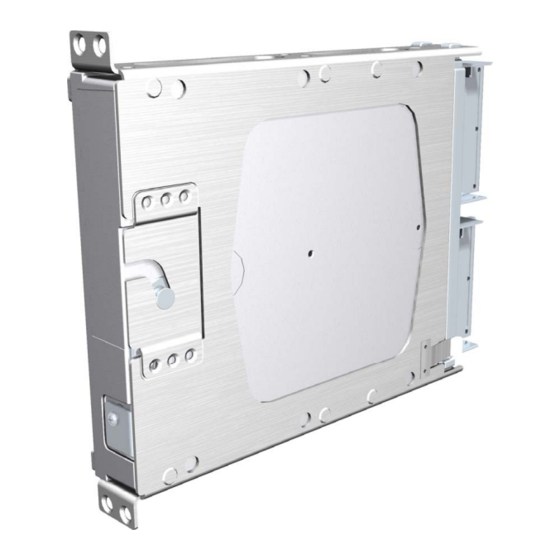
6. Lock the GEA 71 in place using the lever-locking handle. Fasten the handle to the GEA 71 body
using the provided Phillips screw. (Note that some early GEA 71s use D-ring ¼-turn fastener)
Start the handle screw into the hole carefully, to avoid cross-threading. Do not apply
torque in excess of 14 in-lbs to the handle screw. The application of torque exceeding 14
in-lbs to this screw will damage the LRU case and/or retaining hardware.
3.6
Post Installation Configuration and Checkout
The GEA 71 does not provide valid outputs until the aircraft post installation
configuration procedures are completed.
The GEA71 must be installed with a Garmin Integrated Flight Deck and have FAA approved
configuration data. Configuration data is loaded to the GEA 71 from an aircraft-specific SW Loader
Card. GEA settings are predetermined for a specific aircraft and are typically contained within the file
named 'GEA1'.
The PFD serves as the graphics user interface to the installer configuring the system. For basic
configuration information, refer to the G1000 Line Maintenance and Configuration Manual, Garmin part
number 190-00303-04. For actual aircraft installation/checkout, use only aircraft manufacturer approved
checkout procedures.
3.7
Continued Airworthiness
Maintenance of the GEA 71 is "on condition" only. For regulatory periodic functional checks, refer to
approved aircraft maintenance manuals or manual supplements for actual aircraft maintenance
requirements.
GEA 71 Installation Manual
190-00303-40
CAUTION
NOTE
Page 3-3
Revision F
