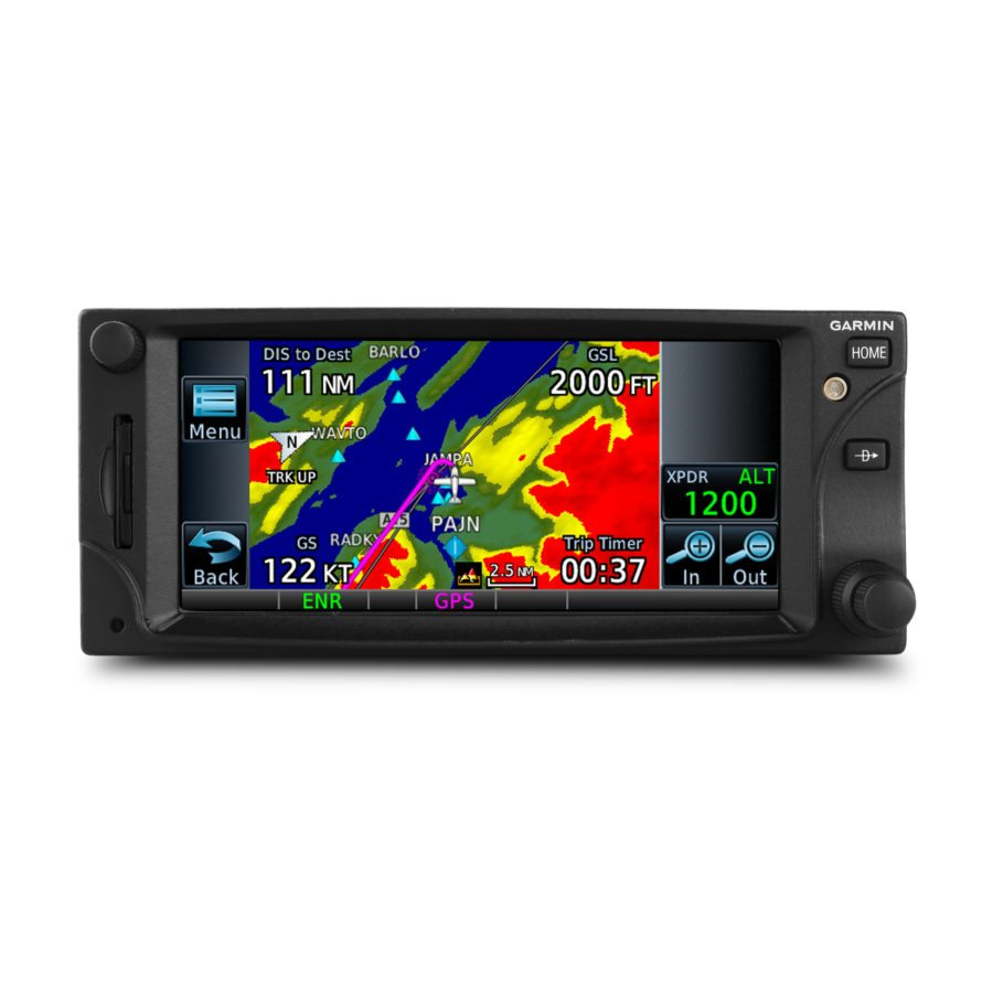
Garmin GTN 7 series Manual de instruções - Página 7
Procurar online ou descarregar pdf Manual de instruções para Ecrã de aviónica Garmin GTN 7 series. Garmin GTN 7 series 22 páginas. Instructions for continued airworthiness for md 369e; md 369f; md 369ff
Também para Garmin GTN 7 series: Manual de instruções (24 páginas)

I
TEM
I
NTERVAL
3. B
R
ATTERY
EPLACEMENT
O
C
N
ONDITION
4. E
B
LECTRICAL
ONDING
C
, GTN/GMA
HECK
B
C
OND
HECK TO BE
PERFORMED IN
A
MD
LIGNMENT WITH
369E/F/FF
MAINTENANCE SCHEDULE
E
10
VERY
YEARS OR
20
100
EVERY
TH
HOUR
,
INSPECTION
WHICHEVER
COMES FIRST
190-01007-KB Rev. 3
Instructions for Continued Airworthiness GTN 6XX/7XX - MD369E/F/FF
D
/P
ESCRIPTION
ROCEDURE
The user must determine by observation when the display brightness is not
suitable for its intended use. Contact the Garmin factory repair station when
the backlight lamp requires service.
The GTN has an internal keep-alive battery that will last about 10 years. The
battery is used for GPS system information. Regular planned replacement is
not necessary.
The GTN will display a low battery' message when replacement is required.
Once the low battery message is displayed, the battery should be replaced
within 1 to 2 months. If the battery is not replaced and becomes totally
discharged, the GTN unit will remain fully operational, but the GPS signal
acquisition time may be increased. There is no loss of function or accuracy
of the GTN unit with a dead battery.
The battery must be replaced by the Garmin factory repair station or factory
authorized repair station.
Perform an electrical bonding check as follows:
1. Remove the GTN and GMA 35 (if installed) from the mounting
rack(s)
2. Remove the backplate assembly from the rack(s) such that the
harnesses are disconnected
NOTE For GTN 7XX only, if the GMA 35 is installed, it must be removed
from its rack and the GMA 35 backplate assembly must be
.
removed prior to performing Step 3. When a GMA 35 bonding
check is planned, perform the GMA 35 bonding check prior to
reinstalling the GTN backplate assembly to the rack.
3. Measure the resistance between each mounting rack and nearby
exposed portion of metallic structure and verify that the resistance
is less than or equal to 10 milliohms.
In the event of bonding test failure, remove the rack and verify that
the countersunk areas around the holes, in the rack that are used to
attach the rack, are free of corrosion or any other debris. Clean the
countersunk areas using P-D-680 (CM234) as specified in MDHI
Model Helicopters Models 369D/E/FF – 500/600N, Basic Handbook
of Maintenance Instructions, CSP-HMI-3 Instruments-Electrical-
Avionics. Reattach the rack to the rails in the panel or pedestal. Re-
verify the resistance between the mounting rack and nearby
exposed portion of aircraft metallic structure and ensure that the
resistance is less than or equal to 2.5 milliohms.
4. Reinstall all backplate assemblies and reinstall the GTN in the
mounting rack.
Page 4 of 19
