Fujitsu ETERNUS LT260 Manual de início rápido
Procurar online ou descarregar pdf Manual de início rápido para Armazenamento Fujitsu ETERNUS LT260. Fujitsu ETERNUS LT260 5 páginas. Tape library
Também para Fujitsu ETERNUS LT260: Manual do utilizador (44 páginas)
Speaker script
ETE-LT260-INM-WBT 02/03/2016
Speaker script
ETERNUS LT260 VIDEO CLIPS
1. Rack installation
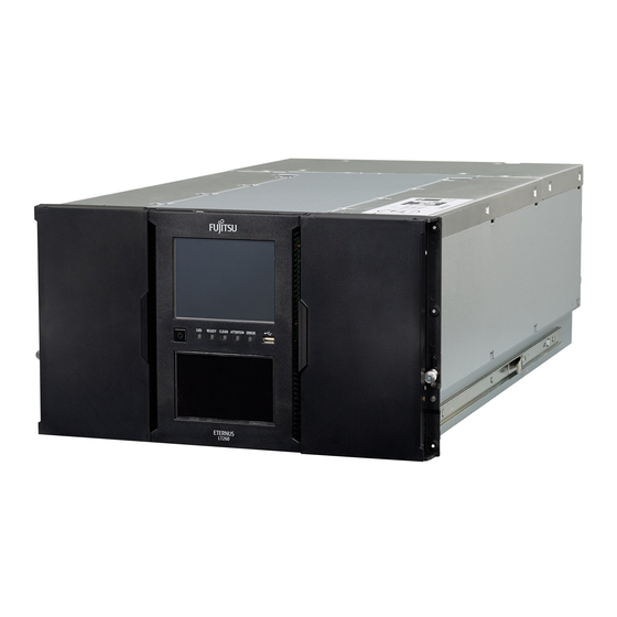
In this film clip we will demonstrate the installation of an LT260 Base Module with one Expansion Module in a Fujitsu PRIMECENTER M1 rack.
Please note that the rack must be of the deeper 700 millimeter type so that the tape library fits in it.
After having unpacked the Base and Expansion Modules from the transportation packaging, one can see that the Expansion Module is open
both from top and bottom.
The Base Module comes always with a cover plate on the top and in the bottom - these remain intact if no Expansion Module is to be used.
The Expansion Module can be fitted either below or above of the Base Module. The decisive factor is in what height of the rack the Base
Module can be installed; convenient access to the OCP should dictate the installation height of the Base Module and consequently the
Expansion Module resides either above or below thereof.
In this film we will install an Expansion Module below of the Base Module and therefore the first step is to remove the lower cover plate from
the Base Module and place it on the underside of the Expansion Module. This can be easiest done when both modules lie on a table upside
down.
To remove, first push down the locking mechanism and then slide the cover towards the front of the library.
Fitting the cover in its place can be done simply by placing the cover leveled with the front of the library and sliding towards the rear of the
system until the locking mechanism snaps out to lock the cover in its place.
For the installation in a rack it is recommended to use a rack installation lift because even when empty the library weighs over 30 kilograms.
Note, for the next steps it is important that the drives are removed to reduce the weight.
After the rack rails have been installed in the rack according to the instructions given in the User Guide, move the sliding assembly to the front
and extend the middle rails all the way out.
Note; when handling the Base Module in the next steps please note that the bottom of the unit is open and therefore the robotic assembly is
exposed to potential damage.
Raise the Base Module to the appropriate height and move it backwards until the inner rails snap in with the sliding assembly. Now push the
releasing levers on both side of the library and push the library inwards until fully in.
Repeat the same procedure for the Expansion Module; please note that when fitted in the rack the gap between the modules must be less than
4 millimeters.
To ensure trouble free movement of the robot between the Modules they must be properly aligned. For this purpose the alignment mechanism
in the back of the upper Module must be loosened and the alignment pin pushed downwards. It is important that the pin can be lowered down
without any feel of resistance, should this not be the case then move the pin back in its upper position, move slightly one of the Modules until
the pin can be lowered without any friction and consequently tighten the thumbscrew.
With both modules in normal operating position, secure them by tightening the thumbscrews on each side of the Modules.
In our example the Expansion Module was ordered without any Drives and the Base Module was ordered with all six Drives configured.
In the next step the Drives must be fitted, technically there are no restrictions; the bays can be populated in any order.
To complete the installation, enable communication between the Base Module and the Expansion Module by connecting the Extension Cable,
connect the signal cables of the drives and finally the power cables; please use the Installation and Operation Guide as reference.
2. Initial Configuration Wizard
After having powered on the tape library for the first time this screen appears on the Operator Control Panel. It is possible to choose between
three IP address areas that will be consequently used exclusively by the LT260, meaning these addresses must not conflict with addresses of
the customer network.
Before the LT260 can be taken into use further parameters need to be set up.
Please note that for demonstration purposes this video clip has been edited and consequently some of the sequences run faster than in real life.
In reality the initial boot phase to the first login screen takes about two and a half minutes and for the library to be ready for use about six
minutes.
Page 1 of 5
Fujitsu Training Academy