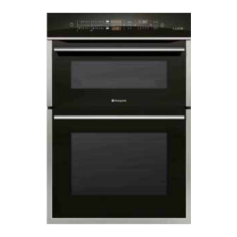
Indesit HOTPOINT LUCE DX1032CX Manual de serviço - Página 26
Procurar online ou descarregar pdf Manual de serviço para Forno Indesit HOTPOINT LUCE DX1032CX. Indesit HOTPOINT LUCE DX1032CX 39 páginas. Built-in touch control electronic multifunction 60 cm double oven

Indesit
Company
FAULT CODES
FAULT
SUBCODE
01
02
11h
12h
21h
22h
51h
52h
54h
56h
F01
57h
58h
59h
61h
62h
63h
64h
65h
66h
67h
90h
1
2
F02
21h
31h
1
01
F03*
02
*
N.B: Open Space appliances only.
1/4
Service Manual UK
DESCRIPTION
Main PCB probe short circuited.
Main PCB probe circuit open.
Rtn out of range
Vline out of range
No mains voltage / Master Relay Fans open
Mains voltage present / Master Relay Fans
shortcircuited /(Fan triac short circuited).
Floor heating element circuit: Triac open or
relay not closing
Circular heating element circuit: Triac open
or relay not closing
Steam heating element circuit: Triac open or
relay not closing
Grill 1 heating element circuit: Triac open or
relay not closing
Grill 2 top heating element circuit: Triac open
or relay not closing
Divider heating element circuit: Triac open
or relay not closing
Ceiling heating element circuit: Triac open
or relay not closing
Floor heating element feedback failure
Circular heating element feedback failure
Steam heating element feedback failure
Grill 1 heating element feedback failure
Grill 2 heating element feedback failure
Divider heating element feedback failure
Ceiling heating element feedback failure
DS / Divider circuit (analogue inputs) out
of range
Visual Board probe short circuited.
Visual Board probe circuit open
uP1 – uP2 communication
Display keys
Visual board setting
Main oven probe short circuited.
Main oven probe circuit open.
26 of 39
CHECKS
1 Unplug, wait for 2 minutes, plug
back in again and test the appli-
ance.
2 Replace the main PCB.
1 Unplug, wait for 2 minutes, plug
back in again and test the appli-
ance.
2 Replace the Display PCB.
3 Replace the Main PCB.
1 Check the PTC probe in the main
cavity (lower) is working properly.
2 Check connectors on the board
and component sides.
3 Check the state of cables.
4 Replace the Main PCB.
English
