2N APS MINI ENTRYCOM Manual do utilizador e de serviço - Página 7
Procurar online ou descarregar pdf Manual do utilizador e de serviço para Unidade de controlo 2N APS MINI ENTRYCOM. 2N APS MINI ENTRYCOM 10 páginas.

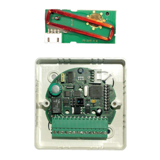
Connecting the mother board with data bus RS485
It is possible to connect data line RS485 to the terminal board box of the module. Up to 32
reading modules 2N APS mini can be connected to this data line, which consists of three
conductors. Each module within the data bus must be assigned a different address by
inserting jumpers on the contacts of X2 connections. The address of a module is given by
the following table:
Jumper
X2.1
X2.2
X2.3
X2.4
X2.5
Jumper
X2.1
X2.2
X2.3
X2.4
X2.5
Sign
in the table means jumper inserted on the connection. After changing an address
it is necessary to reset the module (disconnect and re-connect the power supply)!
Data bus must be connected with cables designed for data transfer (shielded cables or
cables with twisted pairs of conductors). Modules at the end of the data bus (last module
on the line) must contain terminal resistor – jumper inserted on the contacts of the J5
connection. When using certain converters, dividers and repeaters on the RS485 data bus
it might be necessary to insert jumpers on the connections J4 and J6, which define resting
state on the bus. When using a converter supplied by the manufacturer (GNOME485) it is
not necessary to install jumpers on these connections.
Power supply of the mother board
Power supply for the mother board can be provided by the power supply of the door
communicator. The only condition is that this source must have reserve for supplying the
reading module (160 mA) and the door lock (depending on the type). Voltage rating of the
source must be 10 ÷ 15V DC. If the current source does not comply with these conditions,
it is necessary to install new source for the reading module.
Meaning of LED indicators
Color of LED
Constant shining
Red
Blinking with the period of 1s
Fast alternation with green
Yellow
Green
1
2
3
4
17
18
19
20
Mode
HW adress of the module
5
6
7
8
HW adress of the module
21
22
23
24
Online communication via RS 485
Offline operation
Address setting regime
Reading ID medium
Programming regime
7
9
10
11
12
25
26
27
28
Meaning
13
14
15
16
29
30
31
32
