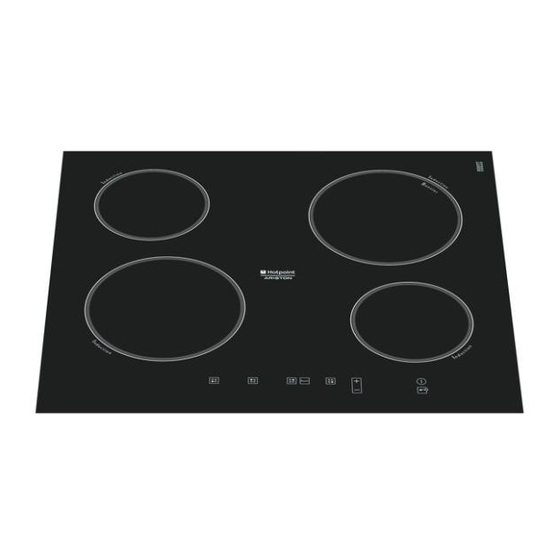
Indesit TIP 642 DD L Manual de serviço - Página 14
Procurar online ou descarregar pdf Manual de serviço para Hob Indesit TIP 642 DD L. Indesit TIP 642 DD L 19 páginas.

FAULT
SUBCODE
F06
3
F07
1
F07
2
F07
3
F08
1
F08
2
F08
3
F09
1
F09
2
F09
3
F10
1
F10
2
F11
1
F11
2
F12
1
Service Manual
Induction hob manual
DESCRIPTION
ISI UART 1 (CN 03): small induction
hotplate not connected
ISI UART 2 (CN 04): hob NTC SC,
large induction hotplate
ISI UART 2 (CN 04): hob NTC OC,
large induction hotplate
ISI UART 2 (CN 04): large induction
hotplate not connected
ISI UART 2 (CN 04): hob NTC SC,
small induction hotplate
ISI UART 2 (CN 04): hob NTC OC,
small induction hotplate
ISI UART 2 (CN 04): small induction
hotplate not connected
Incomplete Power setting fi le
Incomplete VISUAL setting fi le
Incomplete TOUCH setting fi le
ISI UART 1 (CN 03): Heat-sink NTC SC
ISI UART 1 (CN 03): Heat-sink NTC OC
ISI UART 2 (CN 04): Heat-sink NTC SC
ISI UART 2 (CN 04): Heat-sink NTC OC
ISI UART 1 (CN 03): Too high tempe-
rature of the heat-sink
CHECK ACTIONS
1. Check the inductor, verifying that the contacts are well connected
and clean.
2. Check NTC ohmic values (it must not be SC or OC)
3. Replace the inductor if NTC is out of calibration
4. Replace the power board.
NOTE: notifi ed on the corresponding inductor.
1. Check the inductor, verifying that the contacts are well connected
and clean.
2. Check NTC ohmic values (it must not be SC or OC)
3. Replace the inductor if NTC is out of calibration
4. Replace the power board.
NOTE: notifi ed on the corresponding inductor.
1. Check the inductor, verifying that the contacts are well connected
and clean.
2. Check NTC ohmic values (it must not be SC or OC)
3. Replace the inductor if NTC is out of calibration
4. Replace the power board.
NOTE: notifi ed on the corresponding inductor.
1. Check the inductor, verifying that the contacts are well connected
and clean.
2. Check NTC ohmic values (it must not be SC or OC)
3. Replace the inductor if NTC is out of calibration
4. Replace the power board.
NOTE: notifi ed on the corresponding inductor.
1. Check the inductor, verifying that the contacts are well connected
and clean.
2. Check NTC ohmic values (it must not be SC or OC)
3. Replace the inductor if NTC is out of calibration
4. Replace the power board.
NOTE: notifi ed on the corresponding inductor.
1. Check the inductor, verifying that the contacts are well connected
and clean.
2. Check NTC ohmic values (it must not be SC or OC)
3. Replace the inductor if NTC is out of calibration
4. Replace the power board.
NOTE: notifi ed on the corresponding inductor
1. Check the inductor, verifying that the contacts are well connected
and clean.
2. Check NTC ohmic values (it must not be SC or OC)
3. Replace the inductor if NTC is out of calibration
4. Replace the power board.
NOTE: notifi ed on the corresponding inductor.
1. Program Display board again
2. Replace the Display board
1. Program Display board again
2. Replace the Display board
1. Program Display board again
2. Replace the Display board
•
Replace the corresponding generator board.
•
Replace the corresponding generator board.
•
Replace the corresponding generator board.
•
Replace the corresponding generator board.
1. Verify that the fan is correctly wired and that the wiring is intact.
2. Verify that the fan is operative, setting the maximum power.
Edition
2008.03.01
14
Language
English
