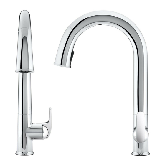
Kohler 72218T-B7-CP Manual de instalação e cuidados - Página 19
Procurar online ou descarregar pdf Manual de instalação e cuidados para Produto de canalização Kohler 72218T-B7-CP. Kohler 72218T-B7-CP 26 páginas. Response electronic kitchen faucet

Troubleshooting
CAUTION: Risk of product damage. This product contains sensitive electronic
components. Use care not to damage pins and connectors during troubleshooting.
CAUTION: Risk of product damage. Do not insert anything other than the sensor
wire into the sensor wire connector (phone jack) on the circuit board.
NOTE: For service parts information, visit your product page at www.kohler.com.
Faucet Troubleshooting Table
Symptoms
1. No water
flow.
2. Low water
flow.
3. Poor spray
pattern.
4. Circuit board
LED is not lit.
Kohler Co.
Probable Causes
A. The supply stops
are closed.
B. Handle is in the
closed position.
C. The hot and/or
cold supply hose
is kinked.
D. The outlet hose
is kinked.
E. Handle LED is
not lit.
F. Sensor LED is
not lit.
G. One or more
screens are
clogged.
A. The supply stops
are partially
closed.
B. Handle is
partially closed.
C. The hot and/or
cold supply hose
is kinked or twisted.
D. The outlet hose
is kinked.
E. One or more
screens are
clogged.
F. Cracked
diaphragm.
A. The spray
nozzles are
clogged.
A. No power to the
circuit board.
B. Power cord is
plugged into a
switched outlet.
Recommended Action
A. Confirm the supply stops are open.
B. Rotate the handle to the open position.
Refer to the "Faucet Operation" section.
C. Confirm the supply hoses are not
kinked. If coiled, maintain an inside
diameter of 3" (76 mm).
D. Confirm the solenoid valve is located
within 7 " (178 mm) to 8" (203 mm)
from the faucet base.
E. Refer to the "Handle Switch
Troubleshooting Table."
F. Refer to the "Sensor Troubleshooting
Table."
G. Refer to the "Cleaning the Screens"
section.
A. Confirm the supply stops are fully
open.
B. Rotate the handle to the full open
position.
C. Confirm the supply hoses are not
kinked or twisted.. If coiled, maintain
an inside diameter of 3 " (76 mm).
D. Confirm the solenoid valve is located
within 7 " (178 mm) to 8" (203 mm)
from the faucet base.
E. Refer to the "Cleaning the Screens"
section.
F. Replace the solenoid valve assembly.
A. Rub your finger over the nozzles with
water running to dislodge debris.
A. Check the power supply connections to
the circuit board.
B. Plug the power cord into an
unswitched 220 VAC outlet (test the
outlet with a radio or other device).
Confirm the circuit board LED
illuminates.
19
1198298-2-C
