Avnet ROHM Semiconductor Manual do utilizador - Página 6
Procurar online ou descarregar pdf Manual do utilizador para Unidade de controlo Avnet ROHM Semiconductor. Avnet ROHM Semiconductor 8 páginas. Power module

2.4 Remote Sense
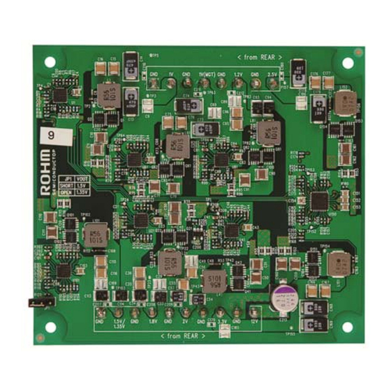
Remote sense is used to compensate for the power supplies being located far from the load. J3
provides a low impedance path directly to the voltage pins on the load. By allowing access to
the voltage actually being seen by the load, the regulator can adjust the output to be more
accurate and compensate for impedance losses through components and the PCB.
When using remote sense, the signals tied to the header are traces that are terminated right at
the pin of the target load. In the Mini-Module Plus case, these voltage pins are terminated right
at the pins on the FPGA. The signals are then routed as traces back to the remote sense
header. It is important that the signals originate from as close to the target load as possible.
The signals on these pins are then used as the set point by the regulators to regulate the output
voltage. By using a signal directly tied to the load as the set point, the power supplies are able
to better regulate the voltage at the intended load.
2.5 Sequencing and Startup
Sequencing of the output voltages follows Xilinx specification for 7 Series devices as follows:
Vccint (1V) -> Vccaux (1.8V) -> Vccaux_io (2V) -> Vcco
The power module is designed to start all remaining supplies after the 2V rail has come up.
The diagram below illustrates the start up sequencing of the power module.
Each rail starts up between 0.2ms and 50ms to meet ramp requirements, as well as have
monotonic rises. The requirement for power down sequencing states that the 3.3V Vcco rail
cannot exceed the 1.8V Vccaux rail during shut down by more than 2.625V for longer than
500ms. No additional power down circuitry is needed in the power module to meet this
requirement.
2.6 Mechanical
The Power Module meets the following geometry requirements:
Copyright © 2012 Avnet, Inc. AVNET and the AV logo are registered trademarks of Avnet, Inc. All other brands are property of their respective owners.
Avnet Electronics Marketing
1V Vccint
1.8V Vccaux
2V Vccaux_io
1.35V / 1.5V Vcco
2.5V Vcco
3.3V Vcco
1V MGT
1.2V MGT
Max Component Height
6 of 8
Timing Diagram
0.4"
Rev A 1.0
06/05/2013
