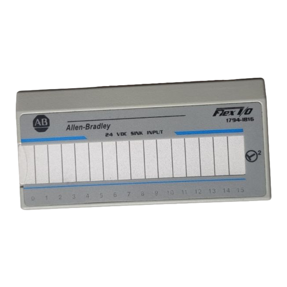
AB Quality 1794-IB16 Manual de instruções de instalação - Página 5
Procurar online ou descarregar pdf Manual de instruções de instalação para Sistemas de E/S AB Quality 1794-IB16. AB Quality 1794-IB16 17 páginas. 24v dc flex i/o digital input modules

24V dc FLEX I/O 16 Sink Input Module 5
Wiring to a 1794 TB3 or TB3S Terminal Base Unit
If you connect or disconnect wiring while the field
WARNING
side power is on, an electrical arc can occur. This
could cause an explosion in hazardous location
!
installations. Be sure that power is removed or the
area is nonhazardous before proceeding.
1. Connect individual input wiring to numbered terminals on the 0–15
row (A) as indicated in the table below.
2. Connect the associated +V dc power lead of the input device to the
corresponding terminal on the 34–51 row (C) for each input as
indicated in the table below. (The +V dc power terminals of row (C)
are internally connected together.)
3. Connect the associated input common (3-wire devices only) to the
corresponding terminal on the 16-33 row (B) for each input as
indicated in the table below. (Commons are internally connected
together.)
4. Connect +V dc power to terminal 34 on the 34–51 row (C).
5. Connect dc return to terminal 16 on the 16–33 row (B).
6. If continuing power to the next terminal base unit, connect a jumper
from terminal 51 (+V dc) on this base unit to terminal 34 on the next
base unit.
7. If continuing common to the next terminal base unit, connect a jumper
from terminal 33 (common) on this base unit to terminal 16 on the
next base unit.
0
1
2
3
4 5
6
7
8 9 10 11 12 13 14 15
0
1
2
3
4
5
6
7
8
9
10
11
16
17
18
19
20
21
22
23
24
25
26
27
34
35
36
37
38
39
40
41
42
43
44
45
1794 TB3
Publication 1794 IN072C-EN-P - October 2001
A
12
13
14
15
0 -15
28
29
30
31
32
33
16-33
B
46
47
48
49
50
51
34-51
C
