COZY W255F and Manual de instruções de instalação e funcionamento - Página 6
Procurar online ou descarregar pdf Manual de instruções de instalação e funcionamento para Forno COZY W255F and. COZY W255F and 20 páginas. Gas-fired vented wall furnace
Também para COZY W255F and: Manual de instruções de instalação e funcionamento (20 páginas)
WARNING:
Do not bypass the blocked flue
switch. To do so could expose the consumer to
property damage, personal iniury or possible death.
Mole than 10' --
R1d_
n
Chimne3_
Kd
_
T
__!
3 i _in.
Chimney--.._._J_%
_e N
above a 3
1oof sm filce
.._ within 10'
o zo ta v
IT
in.
a%
Switcl_ ....
Control
Wire
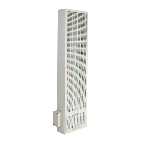
FIGURE B
Man. Reset
Blocked
Flue Switch
_Draft
Diverter
Relief
Opening
Combustion
-Chamber
FIGURE B- 1
ROUGH-IN
INSTRUCTIONS
NOTE: Maximum wall thickness for a dual
wall (W501, W502, W505, W506) installation
is 5-3/8".
STEP 1.
Attach the base plate (purchased
with the vent pipe) to the header plate
using two No. 8 sheet-metal
screws
through
the pre-punched
holes.
The
heater may not vent properly without a
base plate to anchor and seal the vent
system. See Figure C.
Plate cut away fol fili
aidth of stud space to
provide ventilation
SV,lds on 16 inch centels
Sheet metal screw base plate
to header
fastening pipe to base plate
Z
Header plate
of vented wall fiunace
(also acts a_ flrestop)
FIGURE
C
STEP 2.
Cut out an opening
between the
studs of 14-3/8" x 66-1/2" above the floor
plate. Embed the rear flange of the channel
on top of header into either the drywall or
the plastered wall. This provides part of
the required fire stop. Square up and nail
the header in place with the top front of
header located 65-3/4" above floor plate.
(See arrow on right side of header and
Figure 1, 5A and 5B on Page 7).
STEP 3.
Rough in V2"gas supply on center
line of left stud either 4" above top of floor
plate or 4" to right of left stud through floor
plate. See Figure 1 located on Page 7.
Page 6