DeZurik G-SERIES Manual - Página 11

Procurar online ou descarregar pdf Manual para Controlador DeZurik G-SERIES. DeZurik G-SERIES 14 páginas. Lift, turn and reseat used on ptw & pfw tapered plug valves
Também para DeZurik G-SERIES: Instrução (7 páginas), Manual (8 páginas), Manual (17 páginas), Manual (14 páginas), Manual (12 páginas), Manual (16 páginas), Instrução (19 páginas), Manual (17 páginas), Manual de instruções (13 páginas), Manual (9 páginas)
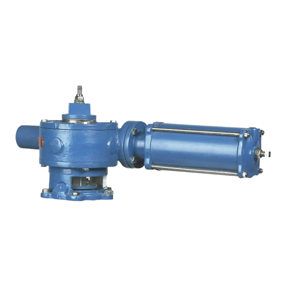
DeZurik G-SERIES Manual
G-Series Manual Actuator used on BOS Butterfly Valves
Actuator Assembly:
1. Install a new seal (B1J) into the housing (B1A).
2. Slide the drive shaft (B1F) into the housing (B1A) and thru bearing race (B1G), thrust bearing
(B1H), bearing race (B1G), worm (B1D), bearing race (B1G), thrust bearing (B1H) and bearing
race (B1G).
3. Rotate the drive shaft (B1F) until the pin holes in the drive shaft and the worm (B1D) line up.
4. Drive the two pins (B1K) thru the worm (B1D) and drive shaft (B1F).
5. Apply removable thread sealant to the threads of pipe plugs (B1I) and install the pipe plugs flush
or below the surface of the housing (B1A).
6. Apply a light film of grease to a new o-ring (B1N) and insert it into the groove in the bottom of
the housing (B1A).
7. Grease the bearing (B1L) in the housing (B1A) and slide the gear (B1C) into the bearing in the
position noted in Step 7. of the ACTUATOR DISASSEMBLY section.
8. Apply a liberal amount of Lithium based grease such as Shell Alvania EP2 or Mobilux EP2 to
the gear (B1C), bearings (B1L) and worm (B1D).
9. Apply a light film of grease to a new o-ring (B1N) and insert into groove in the cover (B1B).
10. Apply a bead of silicone sealant DOW RTV-732 (1055515) or similar to the housing (B1A) or
cover (B1B) mating surface. Grease the bearing (B1L) in the cover, slide the cover onto the
gear (B1C) and fasten with screws (B1M) to the housing.
11. Insert the drive key into the valve shaft/gear (B1C) keyway.
12. Fasten the pointer (B1Q) to the gear (B1C) with the two screws (B1R) in the position noted in
Step 4. of the ACTUATOR DISASSEMBLY section.
13. Install the actuator on the valve as described in the REPLACING ACTUATOR ON VALVE
Section of this Instruction.
D10465
Page 11
DeZURIK
August 2012