DeZURIK
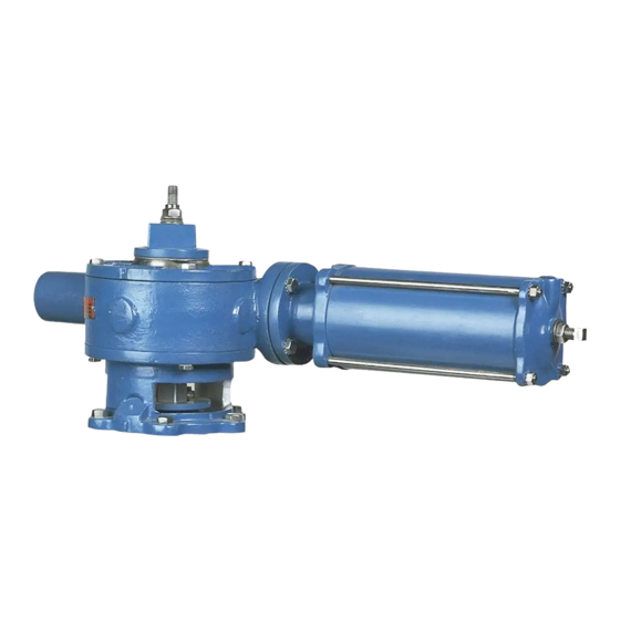
Cylinder Operated G-Series Actuator
Removing Actuator
This valve is a pressure vessel. On 4, 5, 6 and 10" (100, 125, 150 and 250mm) valves, the same
bolts hold both the actuator and the bonnet.
Removing the bolts on 4, 5, 6 and 10" (100, 125, 150 and 250mm) valves before relieving
pipeline pressure can result in personal injury or equipment damage.
Always relieve pipeline pressure before removing the actuator.
6. Remove the screws fastening the adapter to the valve. On the 4, 5, 6 and 10" (100, 125,
150 and 250mm) valves, these screws also hold the bonnet to the valve body.
7. Lift the actuator and adapter off the valve.
Installing Actuator
1. Place the valve in the position it was in when the actuator was removed.
NOTE: Normally this will be so the plug is in the lowest position in the valve body.
2. Line up the scribe marks on the valve and actuator made during actuator removal, then set the
actuator on the valve so that the valve shaft slides into the actuator gear sector.
3. Fasten the actuator adapter to the valve.
4. Slide the pointer and wrenching nut down the plug stud so that it rests on top of the gear sector;
the pointer should point to the correct valve position. If the valve is 24–36" (600–900mm), hold
the keys in position when you slide the wrenching nut over the plug stud and guide the keys into
the gear sector and stem slots. Then install the four screws fastening the wrenching nut to the
gear sector.
5. Place the spring washers on the plug stud as shown in Figure 5.
6. Screw the lock nut down the plug stud until it is tight and the spring washers are completely
compressed, then back the nut off one full turn.
7. If the valve is 24–36" (600–900mm), tighten the #2 lockscrews and then the #1 lockscrews to
hold the keys in place; if the valve is 4–20" (100–500mm), go to step 8. See Figure 4
D10022
(Continued)
Figure 5 – Spring Washer Detail
Page 10
August 2012

