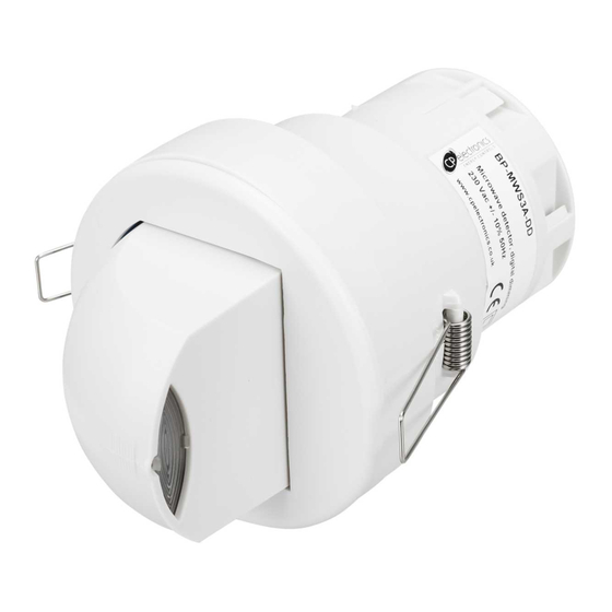
CP Electronics MWS3A-DD Manual do produto - Página 3
Procurar online ou descarregar pdf Manual do produto para Sensores de segurança CP Electronics MWS3A-DD. CP Electronics MWS3A-DD 12 páginas. Direct dim microwave presence/absence detector
Também para CP Electronics MWS3A-DD: Manual de instalação (20 páginas)

Wire the products using the diagrams shown in section 10.
To switch from more than one position simply wire two or more units in parallel using the Live,
Neutral, Switched Live and manual switch wires only. The dimming connection must be wired to
one unit only.
The detector should be sited so that the occupants of the room fall inside the detection pattern
shown in section 11.
Corridors or aisles: the unit should be placed at the end of the corridor or aisle and the sensor
head should be angled to look down the corridor or aisle.
Open plan areas and offices: the unit can be mounted in a corner looking outwards in which
case the sensor head should be angled, or the unit can be mounted in the centre of the area
with the sensor head flat.
Note that the higher the sensor is installed the shorter the detection range will be.
Sites as far away as possible from any lighting or ventilation equipment.
Do not fix to a vibrating surface.
Do not fix to a suspended luminaire.
Site as far away as possible from the surface of metal objects.
Mount using one of the two options overleaf.
1.
Make sure the load is connected and in working order.
2.
Isolate the mains supply to the circuit at the main consumer unit.
3.
Connect the sensor via the terminal blocks. Live supply to the L terminal; load to the L/OUT
terminal; Neutral to the N terminal on the green terminal block. Dimming / external connections
should be made as required according to the applicable wiring diagrams shown in section 10.
4.
Use a small screwdriver to set the LUX level adjuster fully clockwise, the time to minimum (fully
anticlockwise) and the sensitivity to maximum (fully clockwise) using the diagram in section 8.
5.
Apply power—the load should come on immediately.
6.
Vacate the room or remain very still and wait for the load to switch off (should take no more than 2
minutes).
Check that the load switches on when movement is detected.
7.
For dimming applications, set the light output level by using the LUX adjustment thumbwheel or
the handset. See section 9 for handset operation.
During operation the output level varies very gradually. However when the LUX level is
changed the unit automatically enters setup mode: in this mode the output level varies
rapidly. After the setup time the unit reverts to normal.
When adjusting the output, allow the output level to settle by changing very gradually.
To disable the maintained illuminance function completely, set the LUX level to maximum
9.
Select the time out range using the adjuster, fully clockwise is the maximum.
10.
The area of detection can be varied by altering the angle of the sensor head and the sensitivity
adjuster. Note: on maximum sensitivity this unit is extremely sensitive to movement and may
detect through glass, thin walls or partitions. If this causes a problem reduce the sensitivity by
turning the adjuster anticlockwise.
11.
Using the UHS or UHS3 infra-red handset: the override on button turns the unit on permanently;
the override off button turns the unit off permanently; the cancel button cancels the overrides.
When an override is selected an LED will flash inside the unit. The UHS handset can also be used
to set the lux levels—see Section 9.5
Note: the above adjustments can also be made using the DD-LCDHS handset instead of the
manual
3. Wiring & Fixing
4 Installation
page 3
