ABACOM Technologies RF-LPS Manual de início rápido - Página 2
Procurar online ou descarregar pdf Manual de início rápido para Interruptor ABACOM Technologies RF-LPS. ABACOM Technologies RF-LPS 4 páginas. Low power rf controlled switch

Connecting the RF-LPS
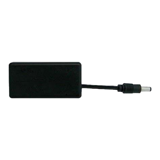
The RF-LPS is patched in series between the load devices power supply and the load device.
Simply connect the external power supply to the 'Supply In' jack on the RF-LPS and plug the out-
put of the RF-LPS in to the supply input of the desired load or device. If the device being switched
through the RF-LPS draws more than 400mA, the RF-LPS output can be used to drive a relay
whose contacts can switch the supply to the load device. The output of the RF-LPS is an open
collector output and includes an internal fly-back diode which is necessary when controlling a re-
lay. The figures below show the open collector output and the method for connecting a device and
a relay.
A device powered through the RF-LPS without the use of a
relay
Setting the Communication Address
The RF-LPS will only respond to valid transmissions matching its configured address. The trans-
mitter and RF-LPS are preconfigured and may not need changing. To set the address, open the
enclosure by removing the two screws on the bottom. On the circuit board there is a row of
switches which may be set to any combination for a desired address. Please note that the ad-
dress set on the RF-LPS must match the address on the hand held RF remote controls (2CH-
REML or TX12E-2C). See TX12E-2C later for additional configuration details. It is advisable to
NOT set address switches to ALL ON or ALL OFF.
Replacing Batteries
The RF-LPS uses two coin type Lithium-Ion 2450 series batteries. To replace, open the enclosure
by removing the two screws on the bottom, and remove the circuit board from inside the enclo-
sure. On one side of the circuit board there will be two battery holders. To remove the batteries,
simply slide them out of their holder. Slide the new batteries in with the negative towards the cir-
cuit board. Feed the antenna back through the hole in the enclosure, insert the circuit board, re-
place the bottom enclosure cover and insert the screws (be careful not to over tighten screws).
ABACOM Technologies, Inc.
A device powered through the RF-LPS using a relay to control
Batteries
Switched Supply Out
•
383 Bering Ave • Etobicoke • ON • M8Z 3B1 • Tel +1(416)236-3858 • Fax +1(416)236-8866
www.abacom-tech.com
more current
Address Switches
Supply In
