Avsl Adastra LA Series Manual do utilizador - Página 4
Procurar online ou descarregar pdf Manual do utilizador para Amplificador Avsl Adastra LA Series. Avsl Adastra LA Series 8 páginas. Loop amplifiers

Installation
The LA series loop amplifiers can be operated free-standing or fitted into a standard 19" rack cabinet using
the supplied rack ears. Ensure that the unit is positioned on a stable surface with adequate cooling
ventilation.
The XLR/jack connectors can be set to accept microphone or line level via the Mic/Line DIP switches (16),
which are also accompanied by switches for activating phantom power (+20V) for use with condenser
microphones.
Multiple loop amplifiers can be used in master/slave mode using the combined slave input/output jack (17).
Connecting a stereo 6.3mm plug to this socket gives 2 wiring options as shown below.
Connecting a mono 6.3mm plug will function as a slave output. A TRS plug with signal connected to the ring
will be needed for a slave input from another loop amplifier.
Alarm contacts (13) are provided, which will emit a siren on the induction loop when the connection is made.
These can be connected to an emergency switch or alarm panel contacts to activate the siren for emergency
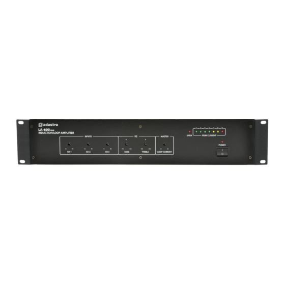
evacuation, indicated by an LED on the front panel (7)
Alongside the alarm contacts are the screw terminals for the induction loop (12). Connect the 2 ends of the
loop wire to these terminals, ensuring no stray strands or shorted connections. See below for details about
installing the loop wire before connecting mains power to the loop amplifier.
Mains is connected via a rear panel IEC connector (11) with a built-in mains fuse.
Use the supplied lead and ensure that the correct mains voltage is set on the voltage selector (10).
There are 3 input channels which can accept inputs via balanced XLR or 6.3mm
jack connection (14) or unbalanced RCA connection(15).
952.864UK, 952.867UK User Manual
