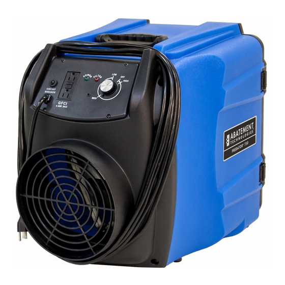
Abatement Technologies PREDATOR PRED750 Manual de instruções - Página 7
Procurar online ou descarregar pdf Manual de instruções para Purificador Abatement Technologies PREDATOR PRED750. Abatement Technologies PREDATOR PRED750 19 páginas. Portable air scrubber

KEY COMPONENT DESCRIPTIONS
1. First Stage Filter. 1" Coarse/Particulate Pre-filter (P/N: F621).
2. Second Stage Filter. 2" Pleated Particulate Pre-filter (P/N: H502). 6. Filter Access Door.
Alternate Second Stage Filter.
•
2" High Capacity Carbon Filter (P/N: VL1002).
3. Final Stage Filter. 99.97% HEPA filter (P/N: H16166-99).
4. HEPA Filter Retaining Brackets.
OPERATING THE UNIT
BEFORE OPERATING THE UNIT
Inspect and tighten any HEPA filter retaining bolts that may have loosened during transportation. Inspect the
filters for any material or structural damage prior to use and replace any damaged filters before operating the
unit. When removing any filters prior to operation, always put them back in place with the airflow indicator on
the filter housing oriented in the proper direction (if applicable).
Be sure to remove the foam plug from the inlet before use. Keep this foam plug so that the inlet can be plugged
again after use to contain any debris that has been capture inside the machine.
As with any air filtration system, external airflow losses not attributable to the air filtration unit will reduce the
airflow of the system. The following recommendations can minimize airflow losses created by external static
resistance.
1. Always use the minimum length of ducting possible with the fewest possible number of turns and bends.
2. Rigid metal ducting creates less turbulence and consequently less airflow loss than flexible ducting.
Regardless of the type of ducting used, rigid, "sweep-type', radiused connections should be used for all
turns and bends.
3. If flexible ducting is used, it must be kept as taut as possible to avoid flattening.
MODES OF OPERATION
1. Negative Pressure – used to help ensure that airborne contaminants do not escape from a contained area
by maintaining negative (lower) air pressure within that area compared to adjacent areas. Any air leakage
will be an inflow of external air, not an outflow of contaminated air. To ensure that the proper pressure
differential is maintained, the volume of HEPA-filtered air exhausted from the containment area must be
the greater of 10% or 100 CFM higher than the volume of air entering. This pressure differential can be
established by:
a. placing the unit inside the containment area and using it to push air out of the containment area.
Attach flex duct at the outlet collar and exhaust the HEPA-filtered air outside of the containment
area according to regulations – outdoors or another location within the building.
b. placing the unit outside of containment area and using it to pull air out of the area. Attach flex duct
between the inlet collar and the containment area.
2. Recirculation – used to reduce concentrations of airborne contaminants in a room or area by continuously
cleaning the air and exhausting it back into the same room or area.
3. Positive Pressure – used to help prevent airborne contaminants from entering a containment area by
maintaining positive (higher) pressure within that area compared to adjacent areas. Any air leakage will be
an outflow of clean air, not an inflow of external air. To ensure that the proper pressure differential is
maintained, the volume of HEPA-filtered air supplied to the area must be the greater of 10% or 100 CFM
higher than the volume of air exhausted. This pressure differential can be established by:
a. placing the unit inside the containment area and using it to pull air into the containment area.
Attach flex duct between the inlet collar and a location outside of the containment area.
b. placing the unit outside of containment area and using it to push HEPA-filtered air into the area.
Attach flex duct at the outlet collar and exhaust the HEPA-filtered air inside of the containment
area.
5. Motorized Impeller.
7. Control Panel.
8. Carrying Handle.
9. Air Intake – 10" nominal diameter.
10.. Exhaust outlet – 10" nominal diameter.
5
