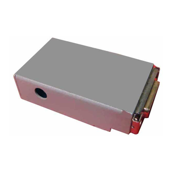
Allied Telesis CentreCOM AT-MC12T Manual do utilizador - Página 3
Procurar online ou descarregar pdf Manual do utilizador para Conversor de multimédia Allied Telesis CentreCOM AT-MC12T. Allied Telesis CentreCOM AT-MC12T 6 páginas.

RJ45—MDI Pinout
Pin
1
2
3
6
4, 5, 7, 8
The transceiver (MAU) attached at the AUI connector must have the
SQE (heartbeat) test disabled for proper operation.
LED Explanation
There are four LEDs next to the 10BASE-T port of the MC12T
LED Name
PWR
LNK
ACT
COL
Power Requirements
The AT-MC12T draws power from the wall-mount AC-DC power
adapter attached at its DC jack. ATI supplies the TUV/UL/CSA
licensed safety compliant AC power adapter for the 120 and 240 VAC
versions with an unregulated output of 12 VDC at 1A. The power
required for the AT-MC12T is:
Installing the AT-MC12T
1. Choose the correct switch settings for the AT-MC12T and the
attached transceiver.
2. Make sure that the SQE test is OFF.
3. Plug the AT-MC12T onto the 15-pin male connector on the
transceiver or on the AUI cable.
4. Slide the connector latch in place.
5. Connect the power adapter to the AT-MC12T and then to an AC
outlet.
Warranty
The AT-MC12T Media Converter has a lifetime warranty. The power
supply has a one year warranty.
Artisan Technology Group - Quality Instrumentation ... Guaranteed | (888) 88-SOURCE | www.artisantg.com
Table 2: RJ45 Pinout
RJ45—MDI-X Pinout
Signal
Pin
TD+
1
TD-
2
RD+
3
RD-
6
N/A
4, 5, 7, 8
NOTE
Table 3: LED Guide
Meaning When LED Is Lighted
Indicates power is applied
Indicates link is established
Indicates data is received on RJ45 or AUI port
Indicates a collision is detected on RJ45 or AUI
port
12 to 18 VDC, 700 mA
Signal
RD+
RD-
TD+
TD-
N/A
