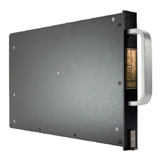
Avtech CSD-714 Selcal Manual de instalação - Página 13
Procurar online ou descarregar pdf Manual de instalação para Conversor de multimédia Avtech CSD-714 Selcal. Avtech CSD-714 Selcal 20 páginas.

- 1. Table of Contents
- 2. Description
- 3. Operation
- 4. Specifications
- 5. Installation
- 6. Installation Testing
- 7. Equipment and Accessory Part Numbers
- 8. Notes for Installation Figures
- 9. Figure 1 - Wiring Diagram
- 10. Figure 2 - Outline Drawing
- 11. Figure 3 - Code Programming
- 12. Figure 4 - 20 Db Attenuator
- 13. Figure 5 - Annunciator Output Circuits
CSD-714 Installation and Operation Manual
NOTES FOR INSTALLATION FIGURES
Note 1 - DECODE PROGRAMMING
Programming the CSD-714 to respond to a selective call is done by connecting the code selection
pins on the rear connector to the CODE SELECT RETURN pin on the rear connector (Pin
MP9B). The SELCAL code is composed of four letters. For instance a code might be FJ-LQ.
The order of the letters within a group of two is not critical, however it is customary to place them
in alphabetical order. There are four rows of pins on the rear connector which set the code. The
rows are 10, 11 13 and 15 and within a row the pins are labeled A,B,C and D. Row 10 programs
the first letter of the selcal code, row 11 the second letter, row 13 the third letter and row 15 the
last letter. Figure 3 has a table of which of the pins (A, B, C, and D) in a row should be connected
to pin MP9B for which code letter. Figure 3 also has an example of which pins are connected for
the example code, FJ-LQ.
Note 2 - LIGHTS IN (Pin MP8A) -- See Figure 5
The internal transistors which control the annunciator lights for the individual channels have their
emitters connected to this pin. If the annunciator lights are to be on steady upon decode, ground
this pin. If it is desired to have the lamps flash, connect this pin to the INTERRUPT OUT (Pin
MP4D) and ground the INTERRUPT IN line (Pin MP4C) as shown in Figure 5.
Note 3 - CHANNEL ANNUNCIATOR LINES -- See Figure 5
The output lines which correspond to the channel annunciators are controlled by internal
transistors whose collectors are connected to the appropriate pin (Pin MP6D, MP7A, MP7B,
MP7C, and MP7D). They are intended to connect to one side of a lamp which has a variable DC
voltage on the other side. Because of the connection described in the section on the LIGHTS IN
line, the voltage on the channel annunciator lines must be more positive that the LIGHTS IN pin
in order for current to flow. These lines can withstand 80 volts in the off condition and will carry
2 amps when on.
Note 4 - EXTERNAL RESETS and SELF TEST
The EXTERNAL RESET input lines (Pins MP1A, MP1B, MP1C, MP1D and MP2A) must be
grounded momentarily when it is desired to reset the associated channel after a decode.
They are internally diode isolated and will withstand the voltages associated with push-to-talk
circuits if it is desired to reset automatically upon selection of the calling radio and transmitting.
1
23-21-01
June 1995
Seattle, WA USA
Rev 1
Page 7
