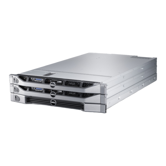
Dell FS7500 Configuração de hardware
Procurar online ou descarregar pdf Configuração de hardware para Armazenamento Dell FS7500. Dell FS7500 2 páginas. Equallogic best practices series network attached storage
Também para Dell FS7500: Manual (18 páginas), Visão geral (7 páginas), Manual técnico (22 páginas)

Setting Up EqualLogic FS7500 Hardware
FS7500 Installation
Before You Begin
This is a condensed reference. Read the Installation Guide (provided in the box) for complete installation information.
Register for an EqualLogic Customer Support account. If you do not have a Customer Service Support account, go to
support.dell.com/EqualLogic and create one. Download and read the PS Series Release Notes from the support site. The Release
Notes contain the latest product information.
Environmental Requirements
Make sure the installation location meets the power, cooling, and ventilation requirements in the Installation and Setup manual, located
in the shipping box.
Required Hardware (Not Supplied)
• 19-inch (48.3 cm) four-post tool-less rack
• Ethernet cables: You need 13 Category 5E or Category 6 Ethernet cables with RJ45 connectors (for each FS7500 controller)
• 2 network switches
Installation Guidelines
The EqualLogic FS7500 hardware configuration consists of two FS7500 Controller units and one FS7500 Backup Power Supply (BPS)
unit. The BPS is required even if you have an uninterruptible power supply system in your environment. Install the three hardware
components adjacent to one another in the same rack.
Additional Information About SANs
For EqualLogic best practices, whitepapers, reference architectures, and sizing guidelines for enterprise applications and SANs, refer
to the Dell Storage Community at http://dell.to/sM4hJT.
1
Unpack the Shipping Box
Caution:
Protect sensitive hardware. Make sure you
use an electrostatic wrist strap or similar form of protection
when handling hardware.
The FS7500 comes packed in one box or two boxes, depending
on your location. In the single box configuration, the BPS is
packed on top of the box containing the controllers.
Place all components on a stable surface.
Controller Contents:
• 2 controller units
• 2 controller bezels
• 6 power cables
• 2 controller rail kits
• Documentation
BPS Box Contents:
• BPS chassis with 2 installed power modules
• Accessory box with bezel, 2 USB cables, 2 hook-and-loop
fastener strips, and 2 REPO port connectors
• Rail kit for the BPS
2
Connect BPS Batteries and Install
the BPS in a Rack
Note:
Install the hardware starting from the bottom of the rack.
You will install the two controllers on top of the BPS.
1. Obtain the rail kit from the BPS shipping box.
2. Remove the power modules from the BPS.
3. Install the rails into the rack.
4. Install the empty BPS chassis into the rack.
5. Connect the battery in each BPS power module:
a. Remove the power module cover. Do not disconnect the
ribbon cable.
b. Remove the battery from the power module.
c. Rotate the battery 180 degrees (turn back to front).
d. Reinstall the battery in the power module.
e. Attach the power module cover.
6. Install the 2 power modules in the BPS chassis.
3
Install the Controllers in the Rack
For each controller, perform the following steps:
1. Obtain the controller rail kit from the controller shipping box.
2. Install the rails in the rack.
3. Pull out the inner sliding rails until they lock into place.
4. Lower the controller onto the rails, starting with the rear.
5. Fit the screws into the J slots on the rails.
6. Slide the controller into the rack.
7. Press the release latch on the side of the rail, and slide the
controller all the way into the rack.
After you install the EqualLogic FS7500 hardware in a rack, it should look similar to the
figure below.
4
Connect the BPS and Controllers to Power
Warning:
Make sure the voltage of your power source is compatible with the voltage rating of the BPS. If the power source voltage
is too low, the BPS will not activate. If the voltage is too high, the BPS can be damaged.
1. Connect each BPS power module to a separate power source using the included power cables.
2. Use the hook-and-loop fastener strips to secure the power cable to the latch on each power module.
3. Turn on the power to each BPS module and make sure it is operational.
For each controller, perform the following steps:
1. Connect the controller to a power source.
2. Connect the controller to the power output
receptacle on a BPS power module.
3. Using one of the USB cables included in the
BPS shipping box, connect the controller to the
USB port on the same BPS power module.
4. Turn on the power to the controller and make
sure it is operational.
1
2
ST: JTKVVN1
Exp Svc Code:
43147463149
Gb
1
Gb
2
Gb
3
Gb
4
To BPS power
module USB
To BPS power
To Power Source 1
module input
1
2
ST: JTKVVN1
Exp Svc Code:
43147463149
Gb
1
Gb
2
Gb
3
Gb
4
To BPS power
To Power Source 2
module USB
To BPS power
module input
REPO OUT
REPO IN
REPO OUT
REPO IN
To Power Source 2
To Power Source 1
