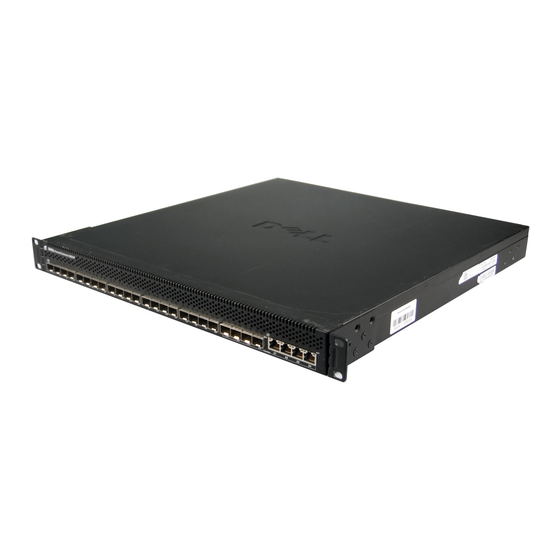
Dell PowerConnect 7048 Atualização do Firmware - Página 21
Procurar online ou descarregar pdf Atualização do Firmware para Interruptor Dell PowerConnect 7048. Dell PowerConnect 7048 24 páginas. Upgrading from version 2.x.x.x or 3.x.x.x or 4.x.x.x or 5.x.x.x to 5.1.9.3 firmware
Também para Dell PowerConnect 7048: Notas de lançamento (27 páginas)

Upgrading PowerConnect Switches from Version 2.x.x.x or 3.x.x.x or
4.x.x.x or 5.x.x.x to 5.1.9.3 Firmware
Switch Recovery Procedure
NOTE:
The Switch Recovery procedure requires one to connect to each
switch individually via the serial port. It will not upgrade stack members other
than the switch directly connected via the serial port. For modular switches,
connect via the serial port on the front panel, not via the CMC. If the switches
are connected via stacking cables, disconnect the stacking cables to perform
the recovery procedure.
1. Connect a serial cable to the serial port (8-No Parity-1-9600-No Flow Control).
a.
For Top-Of-Rack Switches, use the supplied RJ45 Yost to DB9 serial cable. Connect the RJ45 end
to the switch and the DB9 connector to your PC. Set the terminal emulation software to the correct
settings (default setting 9600 baud, 8 data bits, no parity bit, 1 stop bit, and no flow control).
b. For M-Series switches, use the supplied USB Type-A to DB9 serial cable. Plug the USB Type A
connector into the switch and connect the DB9 connector to your PC. Set the terminal emulation
software to correct settings (default setting 9600 baud, 8 data bits, no parity bit, 1 stop bit, and no
flow control). Power cycle the switch by powering it off for at least 10 seconds and then powering
it on.
2. When the boot menu appears, select 2 – Start Boot Menu within 10 seconds of the prompt appearing. If the
boot menu does not appear after power cycling the switch, check the serial port settings and the serial cable
connections. Make sure that RTS/CTS (HW flow control) and XON/XOFF (SW flow control) are disabled
on the terminal. It is preferred to use the serial cable supplied with the switch. If you do not have the
original serial cable, it may be necessary to use a NULL modem device to access the switch via the serial
cable. Check the serial cable setup with an operational switch to verify that it works properly.
3. If 5.1.9.3 firmware has not already been downloaded to the switch, download the firmware to the switch
(Select option 4 - Load new operational code using XMODEM) from the boot menu using Xmodem.
Download the firmware using a 1K block size. HyperTerminal supports Xmodem-1K and is distributed
with Microsoft Windows®. Information on how to operate HyperTerminal can be obtained from Microsoft
at http://technet.microsoft.com/en-us/library/cc784492%28WS.10%29.aspx
4. Select 5 - Display operational code vital product data from the boot menu.
5. Examine the name of the firmware image file listed on the last line of the output and tagged with the
keyword "File." The firmware version is embedded in the name beginning with the lower case letter 'r'
following the switch model number. If the output indicates a 2.x.x.x. or 3.x.x.x version of firmware is
active, select 11 – Activate Backup Image. If the File line at the end of the output indicates a 5.1.9.3 version
of firmware, skip to step 7 without changing the active image.
a.
Example image versions as displayed on the boot menu:
i. "File - PC8024r3v1m4b5.opr" - Version 3.1.4.5
ii. "File – PC6348r2v1m0b7.opr" – Version 2.1.0.7
iii. "File – PC8024r5v1m8b3.opr" – Version 5.1.9.3
iv. "File – PC8024r4v2m2b3.opr" – Version 4.2.2.3
6. Select 7 – Update Boot Code from the boot menu.
7. Select 9 – Reset the system. Do NOT select 1 – Start operational code.
8. Verify that the firmware has been updated to the 5.1.9.3 version using the show version command.
Page 18
