Burkert 2510 Instruções de utilização - Página 3
Procurar online ou descarregar pdf Instruções de utilização para Acessórios Burkert 2510. Burkert 2510 5 páginas. Device socket
Também para Burkert 2510: Instruções de utilização (5 páginas), Instruções de utilização (5 páginas), Manual de Instruções (13 páginas), Manual de Instruções (6 páginas)
Fluid Control Systems
Type 2510
Diagnosis
Operating instructions
ENGLISH
To ensure that the unit functions correctly and will have a long
service life, please comply with the information in these
Operating Instructions, as well as the application conditions
and the permissible data which are specified in the data sheets for the
solenoid valves used, as well as for the Type 2510 Diagnosis device
socket:
• When planning the application of the unit, and during its operation,
observe the general technical rules!
• Work on the unit should only be carried out by specialists using the
correct tools!
• Take adequate measures to prevent unintentional operation or
impermissible impairment!
• Always switch off the supply voltage before carrying out work on the
unit!
• If these instructions are disregarded or if unauthorised work is carried
out on the unit, no liability will be accepted from our side, and the
guarantee on the device and its accessories will become invalid!
The Type 2510 Diagnosis device socket is used for the
detection of flow directions in the Type 6212 solenoid valve.
Medium
LED display
Binary output
Flows
on
"High-Signal" (see Techn. Data)
Does not flow off
"Low-Signal" (see Techn. Data)
Table 1: Function of the Type 2510 Diagnosis device socket
• Direct driving of the Type 6212 solenoid valve via two input terminals
• Setting of the flow threshold to be detected using a potentiometer
(see technical data)
TECHNICAL DATA
Operational voltage
U
e
1)
Protective low voltage
24 V DC
Ripple
max. 10 %
Own consumption
1,5 W
Operational temperature 0 to +50 °C
Connection
Fitting cross-section max. 0,75 mm²
PG16, line cross-section 6-7 mm
Input
Type 6212 solenoid valve
24 V DC protective low voltage
Short-circuit proof binary output / LED display
2)
Flow ("High")
max. Ue - 1 V
min. Ue - 3 V
≤ 1 V
No flow ("Low")
2)
Output current
max. 50 mA
2)
LED off / LED on
No flow / flow
Sensor
≤ 1 sec / 5 sec
Response time / drop-out time
Power consumption
max. 0,4 Watt
Area of application
3)
Medium / medium temperature Water
/ +10 to +60 °C
3)
Lower flow threshold
DN 10
DN 13
DN 20
Upper flow threshold
see K
value of the valve
V
Housing
Insulation / Material
IP 65 / PA
Dimensions
32x32x65 mm
Fixation
M2,5x35 cheesehead screw
Order No.
139 827 J
1)
to VDE 0160
2)
or correct setting
3)
Information about unit variants with higher resolution and for other
media can be obtained from your local Bürkert branch office.
DEAR CUSTOMER
Congratulations on your purchase of this Bürkert unit. For your own
safety, please read carefully through these operating instructions before
installing the unit. Your local Bürkert branch will be pleased to answer
any questions you may have.
not connected
Valve outlet
Figure 2: Pin allocation of the valve output
We reserve the right to make technical changes without
notice
© © © © © Bürkert Werke GmbH Co. All rights reserved
Before working on the Type 2510 Diagnosis device socket,
always switch it free of voltage. Exception: Setting the
potentiometer.
INSTALLATION / PUTTING INTO SERVICE
• Clamp the lines as shown in the connection diagram (Figure 3)
• Switch on the electrical power supply
• Plug in the device socket
SETTINGS (See Figures 3, 3.1, 3.2, 3.3)
NOTE: The solenoid valve must be closed while setting up (no flow)
1. Turn the potentiometer to the left (Fig. 3.1) => LED lights up
2. Turn the potentiometer slowly to the right until the LED goes out (Fig.
3.2)
3. Turn the potentiometer further to the right by one graduation (Fig.
3.3). NOTE: There must be a "Low signal" at the binary output!
4. Open the solenoid valve (Flow) => LED must light up!
NOTE: There must be a "High signal" at the binary output!
ATTENTION! Check these settings regularly every three months
depending on the variations of the medium temperature.
An increase of the medium temperature > 24°C/min can lead to
incorrect messages!
• Secure the device socket using the cheese-head screw
(max. tightening torque 1 Nm).
ATTENTION! When screwing the device socket onto the solenoid
valve, ensure that the seal is properly seated!
Applications affecting Safety
Before using the Type 2510 Diagnosis device socket in systems which
affect safety, please consult your local Bürkert branch!
1)
3 l/min
18 l/min
30 l/min
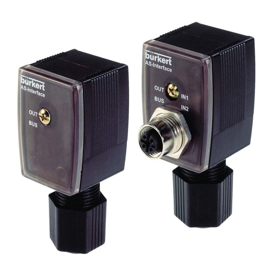
Figure 1: Assembly of the device socket
Potentiometer for adjustment of the flow threshold
Binary output
- Valve
Technical PE *
+ Valve
- GND
+ 24 V
LED
* interference suppression device
Figure 3: Type 2510 Diagnosis
Figure 3.1: Setting 1
Figure 3.2: Setting 2
Figure 3.3: Setting 3
BÜRKERT GERMANY
Chr.-Bürkert-Straße 13-17
Berlin
74653 Ingelfingen
Dortmund
Ph: (0 79 40) 10-0
Dresden
Fax (0 79 40) 10-204
Frankfurt
Hannover
München
Stuttgart
BÜRKERT INTERNATIONAL
A
Ph.
(01) 8 94 13 33
AUS
Ph.
(02) 96 74 61 66
B
Ph.
(03) 3 25 89 00
CDN
Ph.
(9 05) 8 47 55 66
CH
Ph.
(0 41) 7 85 66 66
CZ
Ph.
(06 41) 22 61 80
DK
Ph.
(0 44) 50 75 00
E
Ph.
(93) 3 71 08 58
ET
Ph.
(0 40) 54 27 38
F
Ph.
(01) 48 10 31 10
GB
Ph.
(0 14 53) 73 13 53
HKG
Ph.
24 80 12 02
I
Ph.
(02) 9 52 01 59
J
Ph.
(03) 32 47 34 11
KOR
Ph.
(02) 34 62 55 92
N
Ph.
(0 63) 84 44 10
MAL
Ph.
(04) 6 57 66 49
NL
Ph.
(0 34) 6 59 53 11
NZ
Ph.
(09) 5 70 25 39
P
Ph.
(01) 4 42 26 08
PL
Ph.
(0 22) 6 27 47 20
RC
Ph.
(02) 27 58 31 99
S
Ph.
(0 40) 66 45 100
SF
Ph.
(09) 5 49 70 600
SGP
Ph.
3 83 26 12
TR
Ph.
(02 32) 4 59 53 95
USA
Ph.
(9 49) 2 23 31 00
ZA
Ph.
(0 11) 3 97 29 00
Operating Instructions No. 801 797 01/99/00
Ph: (0 30) 67 97 17 - 0
Ph: (0 23 73) 96 81 - 0
Ph: (03 59 52) 36 30 - 0
Ph: (0 61 03) 94 14 - 0
Ph: (05 11) 9 02 76 - 0
Ph: (0 89) 82 92 28 - 0
Ph: (07 11) 4 51 10 - 0
Fax
(01) 8 94 13 00
Fax
(02) 96 74 61 67
Fax
(03) 3 25 61 61
Fax
(9 05) 8 47 90 06
Fax
(0 41) 7 85 66 33
Fax
(06 41) 22 61 81
Fax
(0 44) 50 75 75
Fax
(93) 3 71 77 44
Fax
(0 40) 54 41 65
Fax
(01) 48 91 90 93
Fax
(0 14 53) 73 13 43
Fax
24 18 19 45
Fax
(02) 9 52 90 33
Fax
(03) 32 47 34 72
Fax
(02) 34 62 55 94
Fax
(0 63) 84 44 55
Fax
(04) 6 57 21 06
Fax
(0 34) 6 56 37 17
Fax
(09) 5 70 25 73
Fax
(01) 4 42 28 08
Fax
(0 22) 6 27 47 20
Fax
(02) 27 58 24 99
Fax
(08) 7 24 60 22
Fax
(09) 5 03 12 75
Fax
3 83 26 11
Fax
(02 32) 4 59 76 94
Fax
(9 49) 2 23 31 98
Fax
(0 11) 3 97 44 28