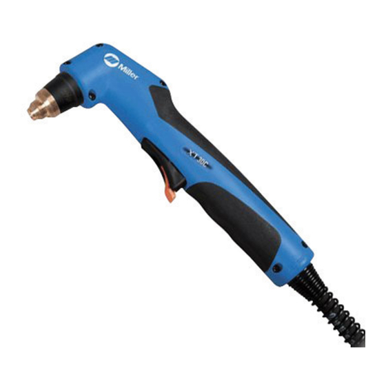
Miller XT30C Manual do Proprietário - Página 20
Procurar online ou descarregar pdf Manual do Proprietário para Lanterna Miller XT30C. Miller XT30C 40 páginas.
Também para Miller XT30C: Manual (40 páginas)

4-8. Electrical Service Guide
Failure to follow these electrical service guide recommendations could create an electric shock or fire hazard. These recommenda-
tions are for a dedicated branch circuit sized for the rated output and duty cycle of the welding power source.
NOTICE − Actual input voltage should not be 10% less than minimum and/or 10% more than maximum input voltages listed in table. If actual input
voltage is outside this range, output may not be be available.
Input Voltage (V)
Input Amperes (A) At Rated Output
Max Recommended Standard Fuse Rating In Amperes
Min Input Conductor Size In AWG
Max Recommended Input Conductor Length In Feet (Meters)
Min Grounding Conductor Size In AWG
Elec Serv 2011−04
Reference: 2011 National Electrical Code (NEC) (including article 630)
1 If a circuit breaker is used in place of a fuse, choose a circuit breaker with time-current curves comparable to the recommended fuse.
2 "Time-Delay" fuses are UL class "RK5" . See UL 248.
3 "Normal Operating" (general purpose - no intentional delay) fuses are UL class "K5" (up to and including 60 amps), and UL class "H" ( 65 amps and
above).
4 Conductor data in this section specifies conductor size (excluding flexible cord or cable) between the panelboard and the equipment per NEC Table
310.15(B)(16). If a flexible cord or cable is used, minimum conductor size may increase. See NEC Table 400.5(A) for flexible cord and cable
requirements.
4-9. Extension Cord Data
.
When calculating max. cord length, remember to include conductor length from line disconnect device to input power receptacle.
Single Phase AC
Input Voltage
115
230
*Conductor size is based on maximum 3% voltage drop
4-10. Primary Changeover Switch
Check input voltage available at site.
1
Changeover Switch
Switch is accessible through slot in rear
panel.
2
Changeover Switch Label
Look at label to find correct switch position.
OM-255 590 Page 16
.
A complete Parts List is available at www.MillerWelds.com
1
2
Time-Delay Fuses
3
Normal Operating Fuses
4
4
6 (13.3)
8 (8.4)
156 (48)
98 (30)
624 (190)
391 (119)
!
Be sure input power connection
meets all
regional, and local electrical codes.
3
Grounded 120 VAC
Receptacle
!
To
use
specifications), connect the unit to
Conductor Size − AWG (mm
10 (5.3)
Maximum Allowable Cord Length in ft (m)
62 (19)
246 (75)
1
applicable
national,
rated
output
(see
50/60 Hz Single Phase
115
230
A 15 or 20
ampere individual
branch circuit
protected by
time-delay fuses
or circuit breaker
is required.
See Section 4-1
(29)
2
)*
12 (3.3)
14 (2.1)
39 (12)
24 (7)
155 (47)
98 (30)
2
Ref. 802 787-C
an individual branch circuit capable
of carrying the effective (eff) current
for the output being used. The unit
must have a properly sized plug
installed and the circuit must be
protected by properly sized fuses
or circuit breakers.
14
15
25
14
96
14
