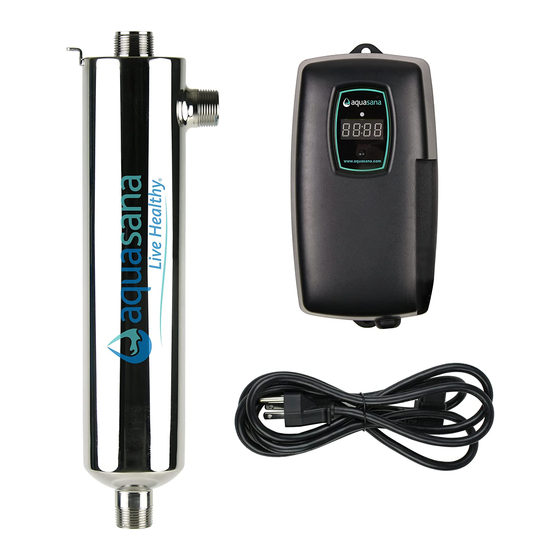
Aquasana AQ-UV-10C Instruções de funcionamento e instalação - Página 8
Procurar online ou descarregar pdf Instruções de funcionamento e instalação para Sistemas de filtragem de água Aquasana AQ-UV-10C. Aquasana AQ-UV-10C 16 páginas. Whole house uv filter
Também para Aquasana AQ-UV-10C: Manual do Proprietário (20 páginas)

Step 6: Once the system has been plumbed in, gently
remove the quartz sleeve from its packaging being careful
not to touch the length with your hands. The use of cotton
gloves is recommended for this procedure as oils from the
hands can leave residue on the sleeve and lamp which can
ultimately block the UV light from getting to the water.
Carefully slide the sleeve into the reactor until you can feel
it hit the opposite end of the reactor. Align the sleeve so its
Figure 4
centered along the length of the reactor, then gently push
Quartz Sleeve
it in to lock it into the internal centering springs in the far
Installation
side of the reactor. CAUTION: Pushing too hard when the
sleeve is not aligned can damage the centering springs. Slide
the o-ring onto the sleeve until it is butted up against the
reactor. (See figure 4.)
Step 7: Hand tighten the provided gland nut over the quartz sleeve onto the
threaded end of the reactor. It has a positive stop to prevent over-tightening. A
firm force may be required to fully tighten the gland nut, but DO NOT USE TOOLS
for this step. Insert the provided stainless steel compression spring into the quartz
sleeve. The spring works with the lamp and lamp connector to create the proper
lamp alignment. PLEASE NOTE: DO NOT install a UV lamp inside the quartz sleeve
without the sleeve spring in place.
Step 8: The reactor is now ready for water flow. When all plumbing connections
have been completed, slowly turn on the water supply and check for leaks. Make
sure the by-pass valves are functioning properly and that the water is flowing
through the reactor. The most common leak is from the o-ring not making a proper
seal on the reactor. For new installations, review steps 6 and 7. For older systems
drain the reactor, remove the o-ring, dry it and reapply silicon grease. Reinstall the
o-ring ensuring that it is properly sealed against the reactor and check again for
leaks.
Step 9: Mount the controller to the wall so it is above or beside the reactor to
ensure that no moisture can deposit on any of the connections (see Figure 1). Always
mount the controller vertically. For monitored systems, insert the sensor connector
into the IEP port located on the right side of the controller. For the sensor to be
recognized by the controller, the controller power must be plugged in last. Do not
plug the controller power cord in before the last step.
Step 10: Always hold UV lamps by their ceramic ends, not by the lamp quartz.
Remove the lamp from its packaging. Again, the use of cotton gloves is
recommended. Be careful to not touch the key's exposed contacts. Insert the UV
lamp into the reactor, being careful not to drop it.
8
