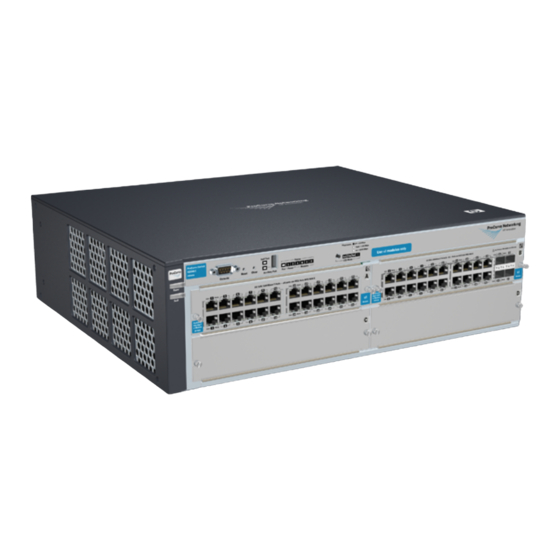
HP 4202vl-48GS Manual de instalação - Página 3
Procurar online ou descarregar pdf Manual de instalação para Interruptor HP 4202vl-48GS. HP 4202vl-48GS 13 páginas.

9/18/2020
Port Type
Cable Type
Copper cables
CX4
Shielded twisted-pair cables complying withthe 802.3ak standard.
1
NOTE:
The Series 4200vl Switch devices are compatible with the IEEE 802.3ab standard including the Auto MDI/MDI-X feature,which allows use of either straight-
through orcrossover twisted-pair cables for connecting to any network devices including end nodes,such as computers, or to other switches, hubs and routers.
Installation location: Before installing the switch, plan its location andorientation relative to other devices and equipment:
In the front of the switch, leave at least 7.6 cm (3 in) of space forthe twisted-pair and fiber-optic cabling.
In the back of the switch, leave at least 10.2 cm (4 in) of spacefor the cl module cabling.
On the sides of the switch, leave at least 7.6 cm (3 in) for cooling.
top
Install switch xl modules
Install switch modules into the slots as shown in the following illustration. For installation details, see the instructions in the manual that
comes with themodule.
CAUTION: Make sure user install only ProCurve Switch vl Modules. Switch gl/xl Moduleswill fit into Switch vl slots, but they will
not operate.
Avoid any electrostatic discharge problems by handling the modules only bytheir bulkheads.
The slot cover can be removed, and the module can be installed with either aflat-bladed or Torx T-10 screwdriver. Retain the slot cover for
future use.
NOTE:
MODULE INSTALLATION NOTE
Any of the supported Switch vl Modules can be installed in any of the slots.
User can install, exchange, or remove modules after the switch has been powered on. Whenever a module is installed during this
process, it isinitialized and tested for correct operation. During this process, the switchSelf Test LED is on. If user hot swap another
module while the switch isinitializing and testing the first module, it is possible to cause the firstmodule or the entire switch to be
reset. To prevent the modules or switch from being reset when user must hot swap multiple modules, follow these precautions:
Do not install/remove any modules from the switch while the switch Self Test LED is lit.
Before removing or installing any modules, make sure that all network cables are disconnected from the module.
The modules employ low-force connectors. Using high force to insert the modules is not needed and should not be used.
Ensure user fully insert the modules. That is, press the module into the slot until the bulkhead on the module is contacting or is very
close to contacting the front face of the switch chassis.
Once the module is fully inserted, ensure that user screw in the two retaining screws to secure the module in place. The screws
should betightened until they are secure, but not overtightened.
If user do not use one or more of the slots, ensure the slot cover plate is still attached over the slot for safe operation and proper
switch cooling. For safety, user should not have more than one module slot uncovered at a time.
1. Insert module into the guides and slide it in until it is fully inserted. High insertion force is not needed and should not be used. For
best results, push near both screws.
Figure 1: Installing a module
Item Number
HPE 4200 vl Switch Series - Installation
Description
Length Limits
0.5 - 15 m CX4
3/12
