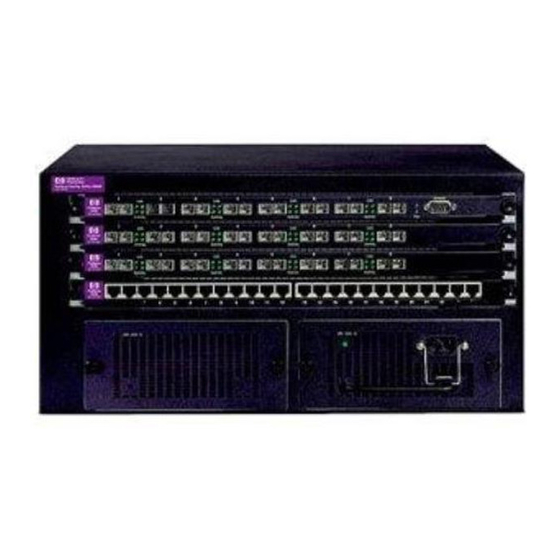
HP ProCurve 9408sl Instruções de montagem - Página 2
Procurar online ou descarregar pdf Instruções de montagem para Interruptor HP ProCurve 9408sl. HP ProCurve 9408sl 2 páginas. Routing switches
Também para HP ProCurve 9408sl: Manual de diagnóstico (2 páginas)

3. Remove the fan control module from the chassis by grasping and pulling integral handles at
the top and bottom of the fan control module faceplate as shown below. Pulling the fan control
module unseats the fan control module connector from a chassis connector.
Remove the fan:
WAR N I N G: To r e d u c e t h e c h a n c e o f c o n t a c t w i t h a s p i n n i n g f a n a n d t o p r e v e n t
e q u i p m e n t d a m a g e , do n o t p e rf o rm t h i s s t e p w i t h t h e f a n c o n t r o l m o du l e i n s t a l l e d .
1. Using the flathead screwdriver, remove the four screws that secure the fan (marked "Fan A"
or "Fan B") to the chassis rear.
2. Remove the fan from the chassis by inserting your fingers underneath the fan enclosure and
pulling the enclosure toward you as shown below. Pulling the enclosure unseats the fan
connector from a chassis connector.
Grasp fan control module here to pull it
out of chassis
Grasp fan enclosure here
to pull it out of chassis
Install the new fan:
1.
Insert the new fan into the fan slot and push the enclosure in until the faceplate is flush with
the chassis. Pushing the enclosure in seats the fan connector with the chassis connector.
2.
Secure the fan to the chassis by tightening the four screws.
Install the new fan control module:
1.
Insert the new fan control module into the fan control module slot, making certain that the
LED on the faceplate is closer to the top of the chassis than the bottom of the chassis.
2.
Push the fan control module in until the faceplate is flush with the chassis. Pushing the module
in seats the module connector with the chassis connector.
3.
Secure the fan control module to the chassis by tightening the two screws. The ProCurve 9408sl
initializes the replaced fan control module automatically.
Verify successful operation:
1.
Observe the LED on the fan control module faceplate to verify that it is operating normally.
The LED should be a steady green, which indicates that the associated fan is working and
responding to the fan control module. If for some reason a replaced fan control module does
not initialize automatically, you can initialize it manually. To manually initialize the fan control
module, access the CLI and enter this global configuration command:
ProCurve RS (config)# fan <fan-number> init
For the <fan-number> parameter, you can specify one of the following:
0 - The system initializes the fan control module associated with fan 0 (labeled "Fan A" on the
chassis)
1 - The system initializes the fan control module associated with fan 1 (labeled "Fan B" on the
chassis)
2 - The system initializes both fan control modules.
Access the CLI and enter the show chassis command to verify that the new fan is operating
2.
normally.
