Alpha Moisture Systems DS1200-AMT Manual de instalação, colocação em funcionamento e operação - Página 5
Procurar online ou descarregar pdf Manual de instalação, colocação em funcionamento e operação para Instrumentos de medição Alpha Moisture Systems DS1200-AMT. Alpha Moisture Systems DS1200-AMT 18 páginas. Dewpoint analysis system

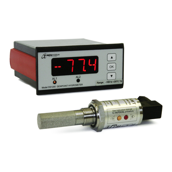
2 DS1200/AMT System Description
•
DS1200 has a 4-digit 14 segment LED display
•
Loop powered Model AMT transmitter DS1200 Input (terminals 45 & 46)
•
DS1200 has 2 Alarm Relays (terminals 21 to 26)
•
DS1200 has mA Output (terminals 11 and 12)
•
Universal Voltage Supply (terminals 31 & 32)
2.1
DS1200/AMT System Application:
•
The DS1200 displays a digital readout of moisture content, derived from the model AMT.
•
Process control with 2 adjustable Alarm set points and an analogue output.
2.2
DS1200 Technical Characteristics:
•
4-digit LED indicator with 13.8mm, 14 segment, characters, programmed to the range of the model
AMT and relay ON/OFF indication.
•
Alarm set points can be adjusted to any application by use of the front keys.
3 DS1200 Mounting:
•
Only technicians who are familiar with the technical terms, warnings, and instructions in the manual
and who are able to follow these should connect the DS1200.
•
Should there be any doubt as to the correct handling of the DS1200, please contact your local
distributor.
•
Mounting and connection of the DS1200 should comply with the national legislation for the mounting
of electric materials, i.e. wire cross-section, protective fuse, and location. Descriptions of Input /
Output and supply connections are shown in the block diagram on page 5 and the instrument top
label.
•
The maximum size of the protective fuse is 10A and, together with the power switch, it should be
easily accessible and close to the DS1200. The power switch should be marked with a label indicating
it will turn OFF the voltage to the DS1200
•
To be mounted in front panels. The included rubber packing must be mounted between the panel
cutout and the display front to obtain IP65 (NEMA 4) ingress protection.
3.1
Installing the Instrument into a Panel
•
Make a cut-out in the donor panel 92.0/92.8 x 45.0/45.6mm (DIN 43700).
•
The maximum panel thickness is 10mm and, if an effective IP65 weatherproof seal is required, the
minimum recommended panel thickness is 1.6mm.
•
Pass the instrument cabinet through the cut-out in the donor panel and slide the panel clamp over the
instrument, from the back.
•
Turn the Red panel clamp screws until the instrument is clamped in position. The screws must be
tightened sufficiently to affect a seal between the front of the donor panel and the back of the
instrument bezel, but never over tightened to the point of fracturing the panel clamp or instrument
case.
NOTE Wires are retained by screws. Ensure that the exposed section of the wire is fully inserted and that no
loose strands are exposed.
4 Wiring
4.1
DS1200 Power Supply
•
Connect the power supply cable to the green 2 terminal block marked 31 and 32 no polarity.
•
The power supply should be 22 to 253 VAC @ 50/60Hz or 20 to 300 VDC
4.2
AMT Sensor Cable
•
Connect the sensor cable to connector slots 45 and 46, ensuring that the red wire connects to pin 46.
Observe that the cage is securely clamped onto the bootlace ferrules on the cable provided.
•
Route the sensor cable to the intended site of the sensor.
Page 2
