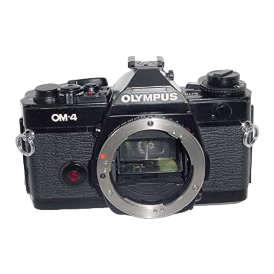
Olympus OM-4 Manual de resolução de problemas - Página 8
Procurar online ou descarregar pdf Manual de resolução de problemas para Câmara digital Olympus OM-4. Olympus OM-4 24 páginas.

Pin 45 is manual speed calibration input from VR-101.
Vcc through 1000 ohm probe should result in fast speed,
Pin 46 is DAC output. See scope trace.
Pin 47 is flash mode signal from shoe contact B- through
1000 ohm probe should set flash mode.
Pins 48 and 49 are TTL flash exposure output,
Pin 50 is sync signal output to trigger flash. Should pulse
low when first curtain runs.
Pin 51 is Vcc in.
Pin 52 is Piezo drive signal. See scope trace,
Pin 53 is CLK out to IC-104,
Pin 54 is power signal to IC-104. Should be low to turn on
display.
Pin 55 is Trigger Switch input. Should pulse low as first
curtain runs. Vcc through a 1000 ohm probe should cause
shutter to latch open,
Pin 56 is reference for Trigger delay.
Pin 57 is output to Q-202 to operate MG-2. Should go
high during exposure, all modes.
Pin 58 is input from Reset Circuit Voltage should pulse
high as mirror rises.
Pin 59 is input from X-sync Switch. Voltage should be
zero with shutter set and high after first curtain has run.
Pin 60 is charge signal to C-201, for MG-1. Voltage will
pulse high at release, then fall to near zero to recharge C-
201.
Pin 61 is release signal to Q-201 for MG-1. Pulses low for
release.
Pin 62 is B- in.
Pins 63 and 64 are offset compensation. Voltage is near
zero.
Pin 65 is reference adjust. Voltage is about 30mv.
Pin 66 is exposure compensation reference current. Near
2.7v.
Pin 67 is ASA input. See scope trace. Voltage is near 2.7v,
Pin§ 68 and 69 are "Auto" adjust connections. Voltage is
near 2.7v.
Pin 70 DAC reference adjust voltage. Typical is near
1.8v.
Pins 71 and 72 are reference current to TV-VR. Typical
voltage is near 1.8v.
Pin 73 is input from TV-VR. See scope trace. B- through
a 1000 ohm probe should result in fast manual speeds.
OLYMPUS OM-4, PAGE 8
Pin 74 is input from AV-VR. Typical voltage is near 1.8v,
B- through a 1000 ohm probe should send bar graph full
scale.
Pin 75 is AV-VR reference current Typical voltage is
1.8v.
Pin 76 input from lock voltage adjustment Typical
voltage is near l.8v.
Pins 77 to 79 are to BV adjustment circuit. Typical
Voltages are near 1.3v to 77 and 78, Near zero for 79.
Pin 80 is Trigger Switch signal to IC-103. Should pulse
low during exposure.
