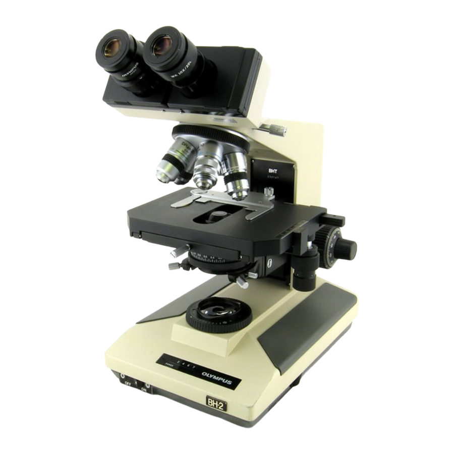
Olympus BH2 Series Desmontagem, limpeza e remontagem completas - Página 15
Procurar online ou descarregar pdf Desmontagem, limpeza e remontagem completas para Microscópio Olympus BH2 Series. Olympus BH2 Series 23 páginas. Phase contrast
Também para Olympus BH2 Series: Manual de resolução de problemas e ajuste (46 páginas), Desmontagem, limpeza e remontagem completas (40 páginas), Desmontagem, limpeza e remontagem (45 páginas), Manual (6 páginas), Manual de instalação (9 páginas)

Figure 41 – Place rollers and rod onto bottom guide rails
Place Focus Block Assembly onto Cylindrical Rollers
Carefully place the focus block assembly, with the guide
block held loosely in place on the back side of the focus
block, onto the cylindrical rollers on the guide rails in
the bottom groove of the arm casting (see Figure 42).
Figure 42 – Place focus block assembly onto rollers
Withdraw about half the length of the guide block from
behind the focus block, making sure to not disturb the
positioning of the two brass shims stuck onto the back
side of the focus block or the guide rails seated in the
side groove of the guide block (see Figure 43).
Figure 43 – Withdraw the guide block about halfway
Complete Teardown, Cleaning, and Reassembly of the Olympus BH‐2 Sliding Focus Block
Place Cylindrical Rollers onto the Upper Guide Rails
IF GREASE IS TO BE USED IN THE SLIDING FOCUS BLOCK (RECOMMENDED):
Lightly coat four of the cylindrical rollers and the
remaining plastic spacer rod with a suitable grease
(item 5 or 7 of
cylindrical rollers onto the greased guide rails in the
groove on top of the guide block, where the guide block
is protruding from the bottom of the arm casting (see
Figure 44, shown without grease for clarity). Orient the
rollers as shown in the photo inset.
IF GREASE IS NOT TO BE USED IN THE SLIDING FOCUS BLOCK:
Place four of the cylindrical rollers onto the guide rails
in the groove on top of the guide block, where the guide
block is protruding from the bottom of the arm casting
(see
Figure
44). Orient the rollers as shown in the
photo inset.
Figure 44 – Place four rollers on the upper guide rails
Use the remaining plastic spacer rod to carefully push
the four cylindrical rollers into the channel formed by
the four guide rails (two in the focus block and two in
the arm casting), making sure that the rollers do not
come out of position on the guide rails as they are
pushed into the channel (see Figure 45).
Figure 45 – Push cylindrical rollers into guide‐rail channel
Appendix
2). Place these four greased
Revision 2
Page 15 of 23
