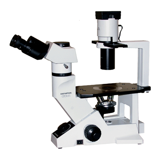
Olympus CKX41 Manual de instruções - Página 28
Procurar online ou descarregar pdf Manual de instruções para Microscópio Olympus CKX41. Olympus CKX41 36 páginas. Reflected fluorescence system
Também para Olympus CKX41: Visão geral (7 páginas), Brochura e especificações (4 páginas), Manual de reparação (43 páginas)

- 1. Table of Contents
- 1. General Precautions for Observation
- 1. Using the Controls
- 2. Important
- 2. Applicable Fluorescence Objectives
- 3. Nomenclature
- 3. Centering the Mercury Burner
- 4. Controls of each Module
- 4. Switching the Filter Slider
- 4. Troubleshooting Guide
- 4. Specifications
- 4. Assembly
- 4. Assembly
- 4. U-Excitation Filter Set Ckx-Nu (Optional)
- 5. Summary of Reflected Fluorescence Observation Procedure
- 5. Proper Selection of the Power Supply Cord
2
25
1
Fig. 17
4
3
Fig. 18
8
Attaching the High-Pressure Mercury Burner
<< Applicable burners >>
· HBO50W/AC (OSRAM)
· CS50W4 (PHILIPS)
CAUTION
Burner type information must be set in the power
supply unit, so check the burner box or burner
base to confirm whether it is of type L1 or L2.
1. Using the Allen wrench, loosen the burner socket clamping
screw 1 and flap open the burner socket section by about
90° in the direction of the arrow.
2. Loosen the burner clamping screws 2 and 3 and remove
the transport post attached to the burner socket.
}To replace the burner, remove the used burner now.
3. Loosen the clamping screw 2 and attach the extremity
without the "UP" marking of the mercury burner 4 so that it
comes on the lower side.
Then, loosen the clamping screw 3 and attach the extremity
marked "UP".
# Do not attach the mercury burner upside down. Other-
wise, the light may become dim and the original perfor-
mance will not be achievable.
In addition, the burner service life may also be shortened.
# Contamination of the burner surface with dirt may cause
its shadow to be cast in the field of view. Be sure to
remove any dirty from the burner surface.
4. Close the burner socket with burner into the original position
and tighten the socket clamping screw 1.
}A click sound is generated when the socket clamping screw
1 is tightened. This sound indicates the normal action of
an interlock switch safety mechanism.
(Figs. 17 & 18)
