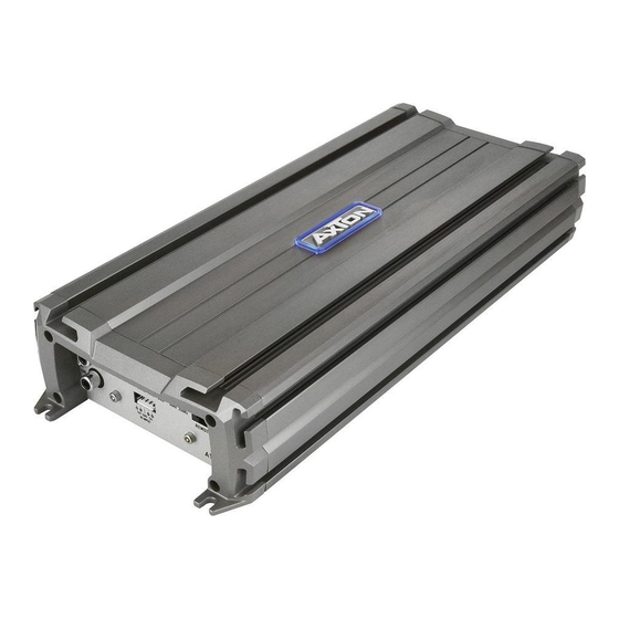
AXTON A250 Manual de instalação e operação - Página 8
Procurar online ou descarregar pdf Manual de instalação e operação para Amplificador AXTON A250. AXTON A250 20 páginas. Car audio system 1-/2-/4-channel power amplifiers

5. CROSSOVER ADJUSTMENTS
For the amplifier to perform best with your speakers, the electronic crossover controls must
be set and adjusted accordingly.
5.1 SELECTING THE OPERATION MODE
You must select and set the appropriate operation mode before you can proceed to
adjust crossover frequency points. This operation mode depends on the speaker system
connected to the respective amplifier channels.
➞ Select HIGHPASS, if the speaker system is a component-, coaxial- or triaxial- type.
➞ Select LOWPASS for a subwoofer system.
➞ Select FLAT If your speaker system will handle a full range signal without electrical or
mechanical overload.
5.2 HIGH PASS CROSSOVER FREQUENCY
For satellite speaker systems, select the "HPF" mode, to cut off the bass content in the
music signal.
Highpass filtering will take away unnecessary mechanical and electrical 'strain' from the
connected coaxial or component speaker systems. Depending on cone surface, voice-coil
diameter and the power handling of the speakers, the following recommendations can be
issued:
FRONT DOOR SATELLITE SPEAKER SYSTEM („HPF" MODE)
13 cm 2-way Component System
16 cm 2- or 3-way Component System
REAR SATELLITE SPEAKER SYSTEM („HPF" MODE)
13 cm 2-way Coaxial or Component System
16 cm 2-way Coaxial or Component System
6x9" or 7x10" Triaxial Speaker System
* When a subwoofer is part of the audio system install.
5.3 LOW PASS CROSSOVER FREQUENCY
Select "LPF", to activate the lowpass filter of the integrated electronic crossover.
The LOWPASS cut-off frequency setting depends on the woofer system and each vehicle is
different! As a rule of thumb, settings in between 60 to 90 Hz will usually give solid results.
The woofer lowpass frequency point is mostly a matter of taste, and must therefore be
'played by ear'.
HP CROSSOVER
FREQUENCY
80 - 110Hz
50 - 80Hz
HP CROSSOVER
FREQUENCY
100 - 120Hz*
100 - 120Hz*
100 - 120Hz*
– 14 –
5.4 SUBSONIC CROSSOVER FREQUENCY (A1300)
Now proceed to adjust the subsonic highpass frequency. This subsonic crossover frequency
point depends on the size and the power handling of the installed subwoofer system. The
higher the subsonic crossover frequency is set, the better or higher mechanical power
handling will result. The trade-off is reduced low end extension! The subsonic highpass
cannot be bypassed. But you can set the potentiometer to a value of 10Hz to make
subsonic filtering completely inaudible.
5.5 BASS BOOST (A1300)
Depending on the size and output capacity of the subwoofer system driven by the A1300
amplifier, it may be sonically beneficial to set the bass boost slide switch into the 6 dB
position, which will emphasize the 40 Hz frequency range output for more „bass punch".
The emphasis at 40 Hz causes a „fatter" bass response, which often creates that extra bit of
fun, depending on the music preferences. By emphasizing the 40 Hz range, the A1300 will
also limit a bit earlier, e.g. the distortion-free output is slightly reduced.
5.6 INPUT GAIN
To reach a maximum in dynamic response from each individual head-unit/amplifier/speaker
combination, it is important to set the respective input sensitivity controls („GAIN") of all
channel pairs correctly.
Before you start, you MUST set all tone controls (Bass, Mid, Treble, Loudness etc.) and the
fader on the head unit to their neutral or center positions.
Now turn all input gain controls of the installed amplifiers anti-clockwise to their minimum
positions and start with the channel pair, that drives the subwoofer system.
SUBWOOFER CHANNEL(S)
Set the volume control of your head-unit to approximately ¾ of full volume, while playing a
dynamic piece of music. Slowly increase the input gain control of the channel pair driving
the subwoofer(s), by turning the GAIN control clockwise. Increase clockwise until the bass
starts to distort. Reduce the main volume level of your head-unit to a medium listening level.
Proceed with further channels, if applicable.
SATELLITE CHANNELS
Slowly increase the input gain control of the channel pair driving the satellite system, by
turning the GAIN control clockwise. Increase clockwise until you reach a good tonal balance
with a slight emphasis of the bass range. Repeat for all further channels.
FINE TUNING OF ALL CROSSOVER FREQUENCY POINT SETTINGS
Finally you can attempt to fine-tune the HP, and LP crossover frequencies on your amplifier
setup, to reach the maximum tonal balance and channel integration of all loudspeakers
connected to your car audio system.
– 15 –
