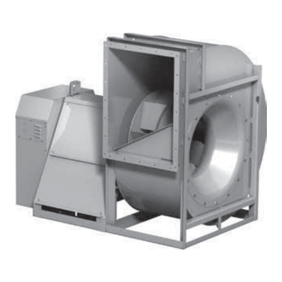
Accurex XUEF-100 Manual de instalação, operação e manutenção - Página 14
Procurar online ou descarregar pdf Manual de instalação, operação e manutenção para Ventilador Accurex XUEF-100. Accurex XUEF-100 20 páginas. Utility fans

Bearing Lubrication Schedule
Shaft bearings are the most critical moving part of a
fan. Therefore, special attention should be given to
keeping the bearings clean and well lubricated. Proper
lubrication provides for reduction in friction and
wear, transmission and dissipation of heat, extended
bearing life, and prevention of rust.
In order for a lubricant to fulfill these tasks, the proper
grease applied at regular intervals is required. See the
recommended bearing lubrication schedule below.
If unusual conditions exist (temperatures below 32°F
or above 200°F), moisture or contaminants - more
frequent lubrication is required.
Recommended Bearing Lubrication Schedule
Relubrication Schedule in Months
Standard Grease
Bearing Bore (inches)
Fan
RPM
1/2 -1
1
1
⁄
- 1
1
8
To 250
12
12
500
12
12
750
12
9
1000
12
7
1250
12
6
1500
12
5
2000
12
3
2500
12
2
3000
12
2
3500
12
1
4000
12
0.5
5000
12
0.25
Number
4
8
of Shots
•
Lubrication interval is based on 12 hour per day
operation and maximum 160°F housing temperature. For
24 hour per day operation, the interval should be cut in
half.
•
Lubricant should be added with the shaft rotating and
until clean grease is seen purging from the bearing.
The lubrication interval may be modified based on the
condition of the purged grease. If bearing is not visible to
observe purged grease, lubricate with number of shots
indicated in chart for bore size.
•
For conditions including high temperatures, moisture,
dirt or excessive vibration, consult the factory for a
specific lubrication interval for your application.
•
Lubricant should be a high quality lithium complex
grease conforming to NLGI Grade 2. Factory
recommends Mobilux EP-2.
•
The use of synthetic lubricants will increase lubrication
intervals by approximately 3 times.
In addition to lubricating the bearings at specified
intervals, set screws in the bearing collars should be
checked for tightness. A bearing collar which has
loosened will cause premature failure of the fan shaft.
Fasteners attaching the bearings to the drive frame
should also be checked.
14
Utility Fans
⁄
1
5
⁄
- 1
7
⁄
1
15
⁄
- 2
3
⁄
2
7
⁄
2
8
8
16
16
16
12
12
12
11
10
8
8
7
6
6
5
4
5
4
3
4
3
2
3
2
1
2
1
0.5
1
0.5
0.25
0.5
0.25
x
0.25
x
x
x
x
x
8
10
16
Variable Frequency Drive
Operation
For operation with a variable frequency drive (VFD),
always check motor amps when adjusting the
operating frequency. Motor may be sized for the
original selected operating speed under 60 Hz.
Bypassing the VFD or increasing the speed from this
original selection, even if less than 60 Hz, may cause
motor to overload or fail. Consult factory with fan
serial number before increasing the upper limiting
frequency.
Always check the fan RPM when adjusting the
operating frequency. Do not exceed maximum class
fan RPM of the wheel.
It is the responsibility of the installing body to
perform coast-down tests and identify any resonant
- 3
frequencies after the equipment is fully installed.
These resonant frequencies are to be removed
from the operating range of the fan by using the
"skip frequency" function in the VFD programming.
Failure to remove resonant frequencies from the
operating range will decrease the operating life of
the fan and void the warranty.
Model XUEFD-100-BI – Variable Speed
Drives
The XUEFD-100-BI comes equipped with a factory
integrated speed controller. Single-phase models
will use a electronically commutated motor and
potentiometer dial to adjust motor rpm. To change
the speed, simply turn the dial. Three-phase models
will offer a mounted, wired and programmed VFD
and premium induction motor. Changing speeds on
a 3-phase model involves pressing the up and down
arrows located on the VFD interface.
Both single- and three-phase versions feature a built-
in electrical disconnect and the option for external
control through 0-10 VDC signal.
NOTE
