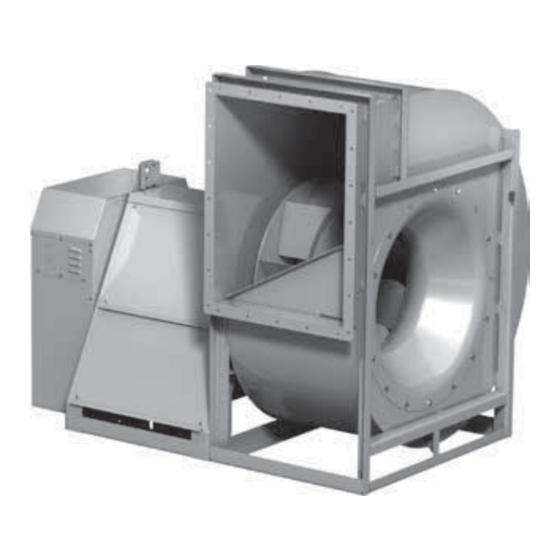
Accurex XUEFD-100 Manual de instalação, operação e manutenção - Página 8
Procurar online ou descarregar pdf Manual de instalação, operação e manutenção para Ventilador Accurex XUEFD-100. Accurex XUEFD-100 20 páginas. Utility fans

Fan Drainage Piping and Trap Detail
(by others)
Fans may have been supplied with an optional drain.
Drains are located at the underside of the scroll
housing. The drain may need to be connected to a
drainage system to ensure proper disposal of any
water or condensate that may occur.
• Drain connections with a plug are 1.0 inch
(25.4 mm) MNPT.
• Installed piping to have a downward angle to allow
for drainage.
• Fill traps to recommended level before start-up.
Note: A conservative method of trap design is to set
N = total static pressure.
Positive Pressure Trap
Connect
this end
to fan drain.
H
H/2
FAN OFF
N = Negative fan pressure (inches W.C.)
H = N - 0.5 inches minimum
Check local codes for proper disposal of drain water
which has been in contact with the exhaust air.
Fans used for grease exhaust need to be equipped
with a separate grease collector.
Drain Options
XUEFD-100
Drain only*
XUEF-100
None
XUEF-300
With plug
None
XUEF-400
With plug
*1.0 inch (25.4 mm) non-threaded drain hole
Electrical Connections
Before electrical connections are made, the supply
voltage, phase and ampere capacity must be checked
for compatibility with the fan motor. In addition, the
supply wiring must be properly fused and conform
to local and national electrical codes. If the unit is
supplied with a safety disconnect switch, ensure
proper wiring to the fan motor. Be sure the disconnect
is switched to the "OFF" position before connecting
supply wires. If no disconnect is supplied, ensure the
supply wire is not live before connection. Supply wires
are then connected to the optional safety disconnect
switch (if supplied) or motor.
8
Utility Fans
1.25 inch
minimum
N
H/2
FAN ON
IMPORTANT
When installing a fan, ensure the proper protective
devices are used to protect personnel from
moving parts and other hazards. A complete line
of protective accessories are available from the
manufacturer including: inlet guards, outlet guards,
belt guards, shaft guards, protective cages and
electrical disconnects.
Electrical Disconnects
All fan motors should have disconnects located in
close visual proximity to turn off electrical service.
Service disconnects shall be locked out when
maintenance is being performed.
Moving Parts
All moving parts must have guards to protect
personnel. Refer to local codes for requirements
as to the number, type and design. Fully secure fan
wheel before performing any maintenance. The fan
wheel may start "free wheeling" even if all electrical
power has been disconnected. Before the initial
start-up or any restart, check the guards (belt, shaft,
inlet and outlet) and check the access doors to
ensure that they are installed and secure.
Installation of UL/cUL 762 Listed
Fans for Restaurant Exhaust
The UL/cUL 762 listing for restaurant exhaust is
available on the XUEF-300 and 400.
UL/cUL 762 fans are listed for a maximum operating
temperature of 400°F (204°C) and includes an access
door and 1 inch (25.4 mm) drain connection. An
outlet guard is strongly recommended when the fan
discharge is accessible. An upblast discharge is
recommended. The fan discharge must be a minimum
of 40 inches (1016 mm) above the roof line and the
exhaust duct must be fully welded to a distance of
18 inches (457 mm) above the roof surface.
Upblast Discharge
Optional Companion
Flange
40 in.**
Weatherhood
(1016 mm)
**Per NFPA 96 the fan discharge must
be a minimum of 40 in. (1016 mm)
above the roof surface.
This drawing is for dimensional information only. See the latest edition
of NFPA 96 Standard for Ventilation Control and Fire Protection of
Commercial Cooking Operations for detailed installation instructions,
materials, duct connections and clearances.
XUEF 300 and 400 models are listed
for grease removal (UL/cUL 762)
File no. MH11745
3 Wheel
Diameters
18 in.*
(457 mm)
Duct
from
*Per NFPA 96 the duct
kitchen
must be of all-welded
hood
construction to a
minimum distance of
18 inches (457 mm)
above the roof surface.
