ABB IED 670 Manual de iniciação - Página 3
Procurar online ou descarregar pdf Manual de iniciação para Controlador ABB IED 670. ABB IED 670 12 páginas.

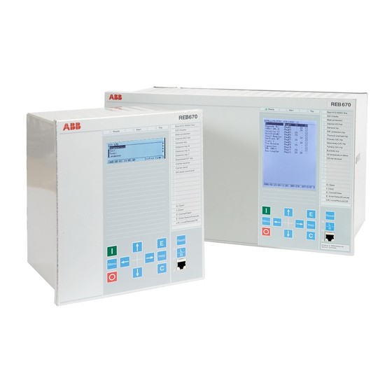
Small size HMI
Medium size HMI
Figure 5: ¨LEDs
1MRK 500 080-UEN rev. -
The Human Machine Interface
The IED 670 products can be ordered with a small or medium HMI module.
Both have a LED panel and a serial communication port on the front panel. The
Parameter Setting Tool in PCM 600 toolbox installed on a PC is used to set
parameters via the serial port. The PC cable to the HMI from the PC shall be a
crossed Ethernet cable with RJ45 connectors. If it is connected via a hub a stan-
dard Ethernet cable is used. The Medium HMI has a 150x180 mm Graphic dis-
play where single line presentation and control of the IED can be shown in
addition to the setting information.
The following keys are provided to navigate the menus:
•
C is used to cancel or clear
•
E is used to confirm or enter
•
L/R is used to set local or remote control
•
Menu alternates between the menu screen and graphic mode
•
Reset activates the reset screen
•
Help activates the help screen
I closes a disconnector or breaker
•
O opens a disconnector or breaker
•
•
The arrow keys are used to navigate between different screens and data
To change a setting, select an item in the menu structure and change it using the
up and down keys on the HMI. After selecting parameter values move up
through the menu system by repeatedly pushing the left arrow key until a dialog
box appears where changes can be confirmed or cancelled.
The LEDs on the front panel of the IED are configured with the Signal Matrix
Tool and are activated by various events, such as Distance protection trip, Phase
selection L1, L2 and L3 and Auto Reclose. The LEDs are labelled according to
the configuration chosen. The label is printed and inserted manually from the
top, see picture. The labels for each LED can include a maximum of 18 charac-
ters in Arial 16 font. These 15 LEDs are alarm indicators and are colored red
(1-6) and yellow (7-15). When active they will show flashing or steady light.
Use the Reset button to reset the LEDs. Above the LCD there is a green
(depends on settings), a yellow (start) and a red (trip) LED. These are activated
by general start and trip operations. The Trip logic function block (TRM) must
be used and set ON to activate the red LED.
3
