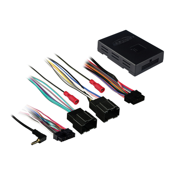
Axxess GMOS-LAN-01 Manual de instruções de instalação - Página 5
Procurar online ou descarregar pdf Manual de instruções de instalação para Equipamento de gravação Axxess GMOS-LAN-01. Axxess GMOS-LAN-01 8 páginas. Gm onstar lan data bus interface

FOR AFTERMARKET RADIO AND AMPLIFIER
(See wiring diagram on page 6)
CONNECTIONS TO BE MADE ON THE 14 PIN HARNESS:
1. Connect the red wire to the ignition/accessory wire of the aftermarket radio.
2. Connect the Orange wire to the illumination wire of the aftermarket radio. If the aftermarket radio
has no illumination wire just tape off the orange wire.
3. Connect the blue/white wire to the amp turn on wire of the aftermarket radio and to the blue/white wire in
the 24 pin harness.
4. White NOT USED
5. White/black NOT USED
6. Gray NOT USED
7. Gray/black NOT USED
8. Connect the Brown wire to the mute wire of the aftermarket radio. If the after market radio does not have a
Mute wire, tape up the Brown wire.
The following wires on the 14 pin harness are for the aftermarket radios that have navigation built in:
1. Connect the Green wire to the parking brake wire of the aftermarket navigation radio.
The following wires on the 14 pin harness are for the aftermarket radios that have navigation built in:
2. Connect the Blue/Pink wire to the VSS or speed sense wire of the aftermarket navigation radio.
3. Connect the Green/Purple wire to the reverse wire of the aftermarket navigation radio.
When completed, plug the 14 pin harness into the GMOS-LAN-01.
CONNECTIONS TO BE MADE ON THE 30 PIN GM HARNESS:
1. Connect the green wire to the amplifier's left rear positive speaker output.
2. Connect the the green/black wire to the amplifier's left rear negative speaker output.
3. Connect the purple wire to the amplifier's right rear positive speaker output.
4. Connect the purple/black wire to the amplifier's right rear negative speaker output.
5. Cut the white wire about half way between the two plugs. Connect the white wire from the 24 pin plug to
amplifier's left front positive speaker output wire. Connect the white wire from the 12 pin plug to the positive
speaker wire of the Metra SP-2003 or equivalent.
6. Cut the white/black wire about half way between the two plugs. Connect the white/black wire from the 24
pin plug to amplifier's left front negative speaker output wire. Connect the white/black wire from the 12 pin
plug to the negative speaker wire of the Metra SP-2003 or equivalent.
GMOS-LAN-01
4
