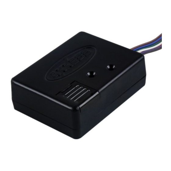
Axxess TRIGGER Manual de instruções de instalação - Página 10
Procurar online ou descarregar pdf Manual de instruções de instalação para Eletrónica para automóveis Axxess TRIGGER. Axxess TRIGGER 19 páginas.

Mode 12: Simple data detector (amp turn on signal from data)
Description: Produces a positive or negative signal out when data is detected.
Note: Output will stay on 3 seconds after data stops transmitting.
Connections:
Interface wiring
Pin 3 (White)
Pin 4 (Pink)
Pin 6 (Green)
Pin 7 (Red)
Pin 8 (Blue)
Pin 9 (Brown)
Mode 13: Long delayed turn-off (for headlights)
Description: This mode will keep headlights on for 1 minute after ignition is turned off.
Connections:
Interface wiring
Pin 2 (Purple)
Pin 4 (Pink)
Pin 5 (Orange)
Pin 6 (Green)
Pin 7 (Red)
Pin 8 (Blue)
Pin 10 (Gray)
To
Ground
Ground
Negative output (500 mA max)
Negative output (500 mA max)
Positive output (2 amp max)
Vehicles data line (see attached diagrams)
To
Ground
Ground
Ground
Negative 1 minute output (500 mA max)
Negative 1 minute output (500 mA max)
Positive 1 minute output (2 amp max)
Headlight switch (negative signal)
