Aybey Elektronik UL180 Manual do utilizador - Página 7
Procurar online ou descarregar pdf Manual do utilizador para Fonte de alimentação Aybey Elektronik UL180. Aybey Elektronik UL180 8 páginas. Emergency power supply for lifts

6- OPERATION
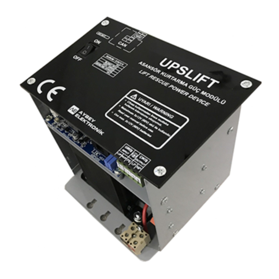
The main switch (MS in Figure 5.1) is power on/off switch of the system. When it is in ON position,
system starts to work as an emergency rescue system. If AC power is present, system bypasses AC
power input to AC output. Otherwise, system generates AC signal from battery voltage and supply AC
output. When MS is in OFF position, only battery charger unit works if AC power input is present.
The battery fuse (BF in Figure 5.1) shuts down the emergency rescue system completely by separating
the batteries from the device. Therefore it should always be in ON position when the device is used.
However when the device is not used for a while, then it is recommended to switch off BF to protect
the batteries for loosing charge.
The device has three separated group of connection terminals. They are AC power input, AC output
and battery connections. AC power input is connected to the line voltage. The batteries are charged
and do not supply any current to the system as long as the line voltage is present. In case of any power
breakdown, UPSLIFT immediately stops charging the batteries and starts to use them as energy source.
Output circuit which supplies energy to the peripherals is always active. The device keeps the output
voltage stable at 220V whatever the line condition is. The device keeps the peripherals in the shaft
unaffected in the transition period where the line power fails.
UPSLIFT will stay alive for one hour after a power breakdown. At the end of this period, it enters sleep
mode to protect the batteries from excessive discharging. However the device can be awaken at any
time when the RESET input is activated manually provided and the main switch is in ON position. It
stays one more hour alive before going to sleep mode again. So the device can be used lots of time for
a period of one hour by resetting until the batteries are getting discharged and unable to drive the
system any more.
Name
LED Indicator
ON
5V
OFF
ON
MCU
OFF
Blinking
ON
ERROR
OFF
ON
BYPASS
OFF
ON
15V
OFF
ON
BAT
OFF
Table 6.1 LED Indicators
Explanation
Board supply is normal.
Board supply is off.
System is powered but the microcontroller is not working.
System is not working.
System is working normally.
There is an error.
No errors.
Line voltage is connected directly to the output circuit. UPSLIFT is not
active.
Output voltage is generated by UPSLIFT.
Internal 15V is present.
Internal 15V failed.
Batteries are connected to the device.
Batteries are not connected or battery fuse is off.
