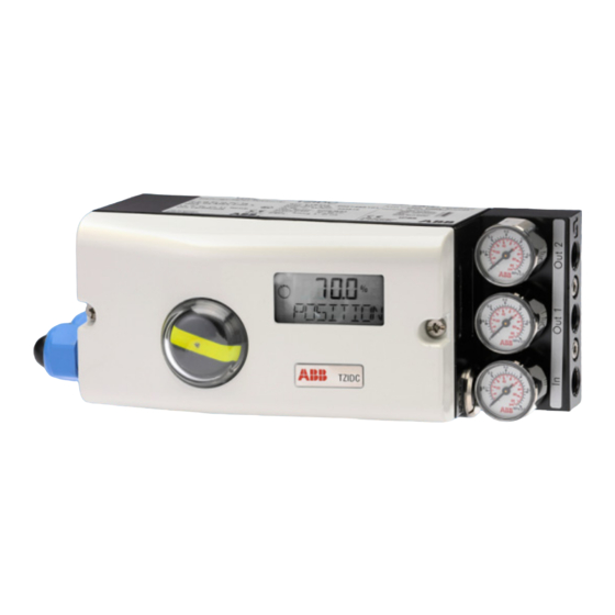
ABB TZIDC Instruções de colocação em funcionamento - Página 2
Procurar online ou descarregar pdf Instruções de colocação em funcionamento para Controlador ABB TZIDC. ABB TZIDC 2 páginas. Digital positioner
Também para ABB TZIDC: Início rápido (2 páginas), Início rápido (3 páginas), Manual de Instruções (10 páginas), Instrução de serviço (4 páginas), Manual (8 páginas)

Commissioning Instructions
Positioner TZIDC, Software Revision 3.00
Commissioning procedure
Always observe all safety instructions and
!
!
precautions in the operating instructions.
1. Turn on the air supply to the positioner.
2. Turn on electrical power supply to the positioner.
Apply the 4...20 mA input signal to the analog input
(terminals +11/-12).
If the emergency shutdown module is installed, the supply
voltage for this module needs to be 24 V DC (terminals
+85 / -86) and the switch needs to be in its center position.
Otherwise, the device has no pneumatic function.
3. Check for proper mounting.
-
Press and hold
MODE
until mode 1.3 (manual adjustment within the sensor
range) is displayed. Then release
-
Press
or
to move the actuator to its mechanical
limit stops in both directions, and note the values. The
angle of rotation is indicated in degrees.
Recommended range:
between -28° and +28° for linear actuators
between -57° and +57° for rotary actuators
Minimum angle: 25°
Important:
The positioner should be mounted/adjusted such that
the portions of the sensor's operating range above and
below the center point are nearly identical. Use the
rotation angle of the position sensor in the positioner to
its utmost extent.
4. Run the standard Autoadjust function
Important:
The standard autoadjustment function described here
is only available with software rev. 2.XX and higher.
For a linear actuator:
-
Press and hold
MODE
display, then release
-
Press and hold
MODE
finished. Then release
Standard autoadjustment is started.
For a rotary actuator:
-
Press and hold
ENTER
the display, then release
-
Press and hold
ENTER
finished. Then release
Standard autoadjustment is started.
When the standard autoadjustment procedure is finished
successfully, the parameter settings are automatically
saved in the non-volatile memory, and the positioner
returns to operating mode 1.1.
If standard autoadjustment should fail, the procedure is
automatically interrupted, and an error code is indicated.
In this case press and hold
positioner returns to mode 1.3 MAN_SENS at the opera-
ting level. Check the assembly for proper mounting and, if
ABB Automation Products GmbH
Schillerstr. 72 · 32425 Minden, Germany
Tel: +49 551 905-534 · Fax: +49 551 905-555
.
Additionally briefly press
.
MODE
, until ADJ_LIN appears in the
.
MODE
again, until the countdown is
.
MODE
, until ADJ_ROT appears in
.
ENTER
again, until the countdown is
.
ENTER
or
for 3 seconds. The
required, readjust it. Repeat the standard autoadjustment
function.
Operating modes
Prodecure for mode selection from operating level:
•
Press and hold
MODE
•
Additionally briefly press
The selected operating mode is indicated.
•
Release
MODE
•
The position is indicated as a percentage or rotation angle
Overview:
Mode
1.0
Adaptive control mode
or
1.1
Fixed control mode
1.2
Manual adjustment
within stroke range
Press
or
to adjust *
1.3
Manual adjustment
within sensor range
Press
or
to adjust *
*) For quick motion: press
The company's policy is one of continuous product improvement and the right
is reserved to modify the information contained herein without notice.
42/18-68 XA
.
as often as required.
Mode display
Position display
¬
C
%
mA
conf
conf
¬
C
%
mA
conf
conf
¬
C
%
mA
conf
conf
¬
C
%
mA
conf
conf
and
together.
Printed in the Fed. Rep. of Germany (02.2009)
¬
C
%
mA
¬
C
%
mA
¬
C
%
mA
¬
C
%
mA
© ABB 2009
