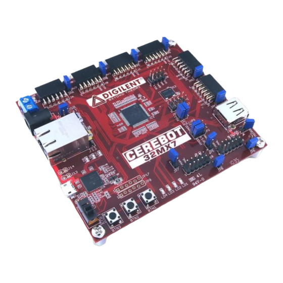
Digilent Cerebot 32MX7 Manual de referência - Página 3
Procurar online ou descarregar pdf Manual de referência para Placa-mãe Digilent Cerebot 32MX7. Digilent Cerebot 32MX7 18 páginas.

Cerebot 32MX7 Reference Manual
USB connector, USB powered from the USB
device connector, or external, non-USB
powered. Jumper block J16, (above the
Ethernet connector, J11) is used to select the
main power source. To select USB powered
from the debug connector, place the shorting
block in the DBG position. To select USB
power from the USB device connector, place
the shorting block in the USB position. This
option is used when the board is being used to
implement a bus powered USB device. To
power the board from an external power
supply, place the shorting block in the EXT
position. The board comes from the factor
jumpered for USB power from the debug USB
connector.
When powering the board from an external
power supply, there are two power supply
connectors that can be used: J17 and J18.
The barrel connector, J17, is used to power the
board from a "wall wart" style power supply.
This type of power supply is available from
many sources. Digilent has an optional power
supply available, the 5V Switching Power
Supply, that can be used with connector J17.
Connector J17 is a 2.5mm x 5.5mm coaxial
connector wired with the center terminal as the
positive voltage.
Connector J18 is a screw terminal connector
for an alternative power supply connection for
use with battery packs, bench supplies or other
power sources where use of a hard wired
power supply is desirable.
The Cerebot 32MX7 is rated for external power
from 3.6 to 6 volts DC. Using a voltage outside
this range will damage the board and
connected devices. For most purposes, when
using external power, a regulated 5V supply
should be used. When operating the board
from an external supply with a voltage other
than 5V, some features of the board won‟t
work.
When the Cerebot 32MX7 is operating as a
USB host, an external power supply connected
to either J17 or J18 must be used to power the
board. In addition to powering the logic on the
www.digilentinc.com
Copyright Digilent, Inc. All rights reserved. Other product and company names mentioned may be trademarks of their respective owners.
Cerebot 32MX7 board, this supply provides the
USB bus voltage supplied to any connected
USB device and must be a regulated 5V with
at least 500mA current capability to meet the
USB specifications.
The CAN bus operates at 5V, and therefore
the transceivers for the two CAN interfaces
require 5V to operate correctly and within the
CAN specification. When using the CAN
network interfaces, the board should be
operated from a 5V supply if using an external
power supply.
Connectors J17, and J18 are wired in parallel
and connect to the "External Power" position
(center position) on the Power Select jumper
block J16. A shorting block should be placed
on the "EXT" position of J16 when using this
option for board power. Only one of the
external power connectors should be used at a
time. If multiple power supplies are connected
simultaneously, damage to the board or the
power supplies may occur.
The power supply selected by the shorting
block on J16 will appear on the input power
supply bus, labeled VIN in the schematic. This
voltage is regulated to 3.3V to power the
debug circuit by IC11, a Microchip MCP1801
Low Dropout voltage regulator. This regulator
is turned on and the debug circuit is powered
whenever the power switch is in the on
position.
The USB specification requires that USB
devices not draw more than 100mA of current
until they have enumerated on the USB bus
and told the host that they want to consume
more current. To meet this specification, the
debug circuit turns on main board power by
driving the PWR_ON signal high after
successfully enumerating on the USB bus. The
bus labeled on the schematic as VCC5V0 is
switched on when this occurs. The VCC5V0
bus powers the input to the main board voltage
regulator, the input voltage to the USB bus
voltage load switch used when using the board
as a USB host, the power supply voltage for
the CAN transceivers, and the 5V0 side of the
power select jumpers for the Pmod connectors.
page 3 of 17
