Digilent chipKIT uC32 Manual de referência - Página 10
Procurar online ou descarregar pdf Manual de referência para Placa-mãe Digilent chipKIT uC32. Digilent chipKIT uC32 18 páginas.

chipKIT™ uC32™ Board Reference Manual
As described earlier, reset of the PIC32 microcontroller can be initiated by the USB serial converter. The USB serial
converter brings the DTR pin low to reset the microcontroller. Jumper JP1 can be used to enable/disable the ability
for the USB serial converter to initiate a reset.
The P32_RST net is connected to pin 3 of connector J2. This allows circuitry on a shield to reset the
microcontroller, or to ensure that the circuitry on the shield is reset at the same time as the microcontroller.
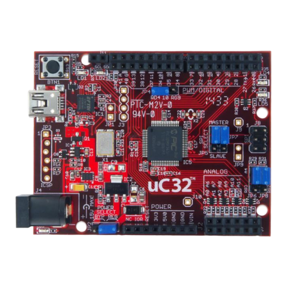
Connector J8 provides access to the SPI bus. Pin 5 provides access to the SPI Slave Select signal (SS).
On Arduino boards, the corresponding connector is also used as an in-system programming connector as well as
providing access to some of the SPI signals. On Arduino boards, pin 5 of this connector is connected to the reset
net.
Some Arduino shields, notably the Ethernet shield, connect pin 5 to the reset net on pin 3 of connector J2. This
causes the processor to be reset each time an attempt is made to access the SPI port. Jumper JP9 can be used to
break the connection between J8 pin 5 and reset when using Arduino shields that make this connection. JP9 has a
cuttable trace on the bottom of the board that can be cut to break the connection between SPI SS and reset. JP9 is
not loaded at the factory. To restore the connection, solder a two pin header at the JP9 position and install a
shorting block. A reset button is at the upper left corner of the board. Pressing this button resets the PIC32
microcontroller.
3.6
Microchip Development Tool Compatibility
In addition to being used with the MPIDE, the uC32 board can be used as a more traditional microcontroller
development board using Microchip Development Tools.
Unloaded connector JP3 on the left side of the board is used to connect to a Microchip development tool, such as
the PICkit3™, for in-circuit serial programming (ICSP). The holes for JP3 are staggered so that a standard 100-mil
spaced 6-pin header can be press fit to the board without the need to solder it in place. Any Microchip
development tool that supports the PIC32 microcontroller family, and can be connected via the same 6-pin
interface as the PICkit3, can be used.
Typically, a right-angle male connector is used in JP3 so that a PICkit3 can be attached coplanar with the uC32
board. If the connector is loaded from the top, the PICkit3 will be upright (button and LEDs visible). Alternatively,
the connector can be loaded from the bottom. In this case, the PICkit3 will be upside down.
If JP3 is loaded from the top, the PICkit3 will interfere with the USB connector and the external power connector. A
short six-wire cable can be used between the PICkit3 and the uC32. If JP3 is loaded from the bottom, the PICkit3
won't interfere with the USB and external power connectors.
®
®
The Microchip MPLAB
IDE or the MPLAB
X IDE can be used to program and debug code running on the uC32
board. These programs can be downloaded from the Microchip web site.
Using the Microchip development tools to program the uC32 board will cause the boot loader to be erased. To use
the board with the MPIDE again, it is necessary to program the boot loader back onto the board. The boot loader
image can be downloaded from the Digilent Uno32 product page.
Copyright Digilent, Inc. All rights reserved.
Page 10 of 17
Other product and company names mentioned may be trademarks of their respective owners.
