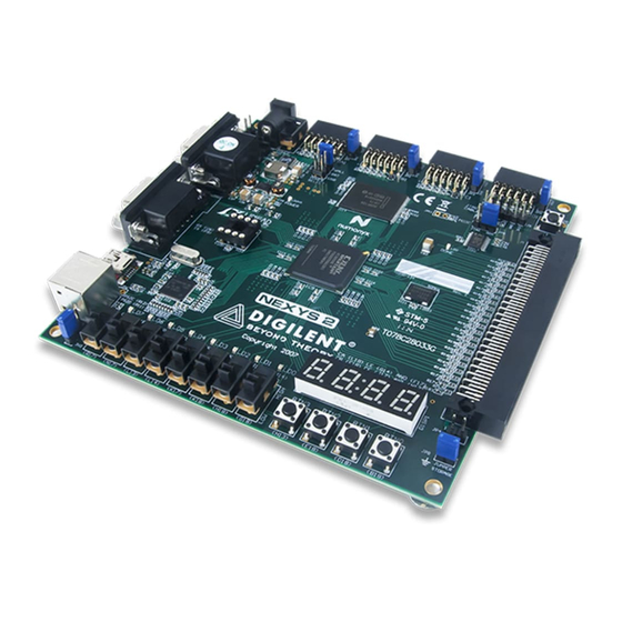
Digilent Nexys2 Manual de referência - Página 3
Procurar online ou descarregar pdf Manual de referência para Placa-mãe Digilent Nexys2. Digilent Nexys2 18 páginas.

Nexys2 Reference Manual
more than 100mA will be drawn through the USB cable (as required by the USB specification). A USB
host can supply only 500mA of current at 5VDC. When using USB power, care must be taken to
ensure the Nexys2 board and any attached peripheral boards do not draw more than 500mA, or
damage to the host may result. The Nexys2 board typically consumes about 300mA of USB current,
leaving about 200mA for peripheral boards. If peripheral boards require more current than the USB
cable can supply, an external power supply should be used.
The Nexys2 board uses a six layer PCB, with the inner layers dedicated to VCC and GND planes.
The FPGA and the other ICs on the board all have a large complement of bypass capacitors placed
as close as possible to each VCC pin. The power supply routing and bypass capacitors result in a
very clean, stable, and low-noise power supply.
FPGA and Platform Flash Configuration
The FPGA on the Nexys2 board must be configured (or programmed) by the user before it can
perform any functions. During configuration, a "bit" file is transferred into memory cells within the
FPGA to define the logical functions and circuit interconnects. The free ISE/WebPack CAD software
from Xilinx can be used to create bit files from VHDL, Verilog, or schematic-based source files.
The FPGA can be programmed in two ways:
directly from a PC using the on-board USB port,
and from an on-board Platform Flash ROM (the
Flash ROM is also user-programmable via the
USB port). A jumper on the Nexys2 board
determines which source (PC or ROM) the
FPGA will use to load its configuration. The
FPGA will automatically load a configuration
from the Platform Flash ROM at power-on if the
configuration Mode jumper is set to "Master
serial". If the Mode jumper is set to "JTAG", the
FPGA will await programming from the PC (via
the USB cable).
Digilent's freely available PC-based Adept
software can be used to configure the FPGA
and Platform Flash with any suitable file stored
on the computer. Adept uses the USB cable to
transfer a selected bit file from the PC to the FPGA or Platform Flash ROM. After the FPGA is
configured, it will remain so until it is reset by a power-cycle event or by the FPGA reset button
(BTNR) being pressed. The Platform Flash ROM will retain a bit file until it is reprogrammed,
regardless of power-cycle events.
To program the Nexys2 board using Adept, attach the USB cable to the board (if USB power will not
be used, attach a suitable power supply to the power jack or battery connector on the board, and set
the power switch to "wall" or "bat"). Start the Adept software, and wait for the FPGA and the Platform
Flash ROM to be recognized. Use the browse function to associate the desired .bit file with the FPGA,
and/or the desired .mcs file with the Platform Flash ROM. Right-click on the device to be
programmed, and select the "program" function. The configuration file will be sent to the FPGA or
Platform Flash, and the software will indicate whether programming was successful. The configuration
Copyright Digilent, Inc.
Cypress
EZ-USB
USB miniB
JTAG
connector
XCF02
Platform
Flash
Figure 4: Nexys2 programming circuits
Page 3/17
www.digilentinc.com
JTAG
Mode
header
Jumper
Spartan 3E
FPGA
JTAG
PROG
port
Slave
serial
DONE
port
Done
LED
Doc: 502-134
Digilent
Vdd
FPGA
Reset
Button
(BTNR)
