Digilent PmodUSBUART 410-212 Manual de referência - Página 2
Procurar online ou descarregar pdf Manual de referência para Unidade de controlo Digilent PmodUSBUART 410-212. Digilent PmodUSBUART 410-212 2 páginas.

PmodUSBUART™ Reference Manual
3
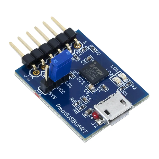
SYS3V3 Select (Header JP1)
The board attached to the PmodUSBUART can have its 3.3V rail powered by the header JP1. If jumper JP1 is set to
SYS, then the SYS3V3 pin is powered by the VCC outputted by the FTDI chip. If the board attached to the
PmodUSBUART is powered on its own, the jumper should be set to LCL.
4
LEDs
There are two LED indicators on the PmodUSBUART. LD1 indicates a data transfer from the micro-USB connector
(J1) to the UART connector (J2). LD2 indicates a data transfer from the UART connector (J2) to the micro-USB
connector (J1).
Copyright Digilent, Inc. All rights reserved.
Other product and company names mentioned may be trademarks of their respective owners.
Connector J2 – UART Communications
Pin
Signal
1
RTS
2
RXD
3
TXD
4
CTS
5
GND
6
SYS3V3
Table 1. Pinout description table.
Description
Ready to Send
Receive
Transmit
Clear to Send
Ground
Power Supply (3.3V)
Page 2 of 2
