Fiber Options S711D Manual de instruções - Página 7
Procurar online ou descarregar pdf Manual de instruções para Sistema de microfone Fiber Options S711D. Fiber Options S711D 14 páginas. Universal data
continued from page 1
515R1 and 517R1 Card Cage Racks
CAUTION: Although a rack card may be installed without
turning off power to the rack (hot-swappable), Fiber
Options recommends that the power switch on the rack
power supply is turned OFF and that the rack power supply
is disconnected from any power source.
1. Make sure that the card is oriented right-side up, and
slide it into the card guides in the rack until the edge con-
nector at the back of the card seats in the corresponding
slot in the rack's connector panel. Seating may require
thumb pressure on the top and bottom of the card's front
panel.
CAUTION: Take care not to press on any of the LEDs.
2. Tighten the two thumb screws on the card until the front
panel of the card is seated against the front of the rack.
501R Standalone Enclosures
CAUTION: Fiber Options recommends that the enclosure
is not connected to any power source during installation.
1. Look inside the enclosure to determine the location of
the socket for the edge connector on the card. Orient the
card so that it will seat in the socket, and slide it into the
enclosure until the edge connector at the back of the card
seats in the socket. Seating may require thumb pressure
on the ends of the card's front panel.
CAUTION: Take care not to press on any of the LEDs.
2. Tighten the two thumb screws until the front panel of the
card is seated against the front of the enclosure.
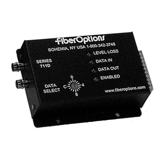
MODULE SETUP
Data Selection
NOTE: The Data Selection switch on standalone units, or
SW1 on rack cards, is shipped in the Disabled setting.
Using the rotary Data Select switch, select a valid data for-
mat according to the Data Select Settings in Figure 4.
NOTE: If the link is going to support RS485, refer to
NOTES ON RS485 APPLICATIONS.
Fiber Options
Data Translation
The data translation capability of the S711D series is
unique in the industry. It allows translation from one format
to another, thus eliminating the requirement for external
translation devices.
The translation is in the physical layer only; it cannot inter-
pret specific protocols, nor do command translations. Due
to the encoding schemes utilized in Manchester and
Biphase, these formats are exempt from translation. Data
translation examples are shown in Table 19.
Alarm Jumper
Rack cards are supplied with an alarm function that goes
active if the optical signal input to the receiver fails. The
alarm is always indicated on the front panel of the card by
a red Level/Loss
TM
LED. The alarm may also be output to
the rack power supply, where a sonalert (audible alarm)
and alarm output contact closure may be activated.
The alarm is set to ON at the factory. If the alarm output is
not desired, remove jumper J4 from pins 1 - 2 and store the
jumper on pins 2 - 3. Refer to Figure 2.
NOTE: Removing jumper J4 does not affect the operation
of the Level/Loss
LED. Loss of optical signal will always
TM
be indicated by a red Level/Loss LED.
CONNECTIONS
Data Connections: Connect the data cable to the remov-
able 8-pin or 10-pin screw terminal on the S711D accord-
ing to Tables 1 - 18 for the data format selected above.
Fiber Optic Cable Connection: Most cable manufacturers
identify the individual fibers in the cable. Select appropri-
ately terminated fiber and mark both ends with unique iden-
tification label (e.g. for cable no. 03, fiber no. 08) to ensure
that the fiber connected to the near end is the same one
that is connected to the far end. The proper optical con-
nection will link the transmitter's OUT port to the receiver's
IN port.
1.
Wipe the inside of the port's sleeve with a lint-free
pipe cleaner moistened with reagent-grade isopropyl alco-
hol. Blow dry with dry air.
2.
Clean the connector using a lint-free cloth dampened
with alcohol to thoroughly wipe the side and end of the fer-
rule. Blow the ferrule dry with dry air. Visually inspect the
ferrule for lint.
3.
Fasten the fiber optic cable to the port.
5