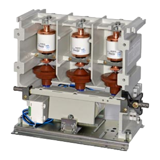
Siemens 3TL81 Manual de Instruções - Página 13
Procurar online ou descarregar pdf Manual de Instruções para Equipamento industrial Siemens 3TL81. Siemens 3TL81 20 páginas. High-voltage vacuum contactors

Fig. 8 Erdanschluß des Vakuumschützes
Earthing connection of vacuum contactor
Anschließen der Klemmenleiste
Die Magnetspule ist bereits an der Klemmenleiste des elektro-
nischen Sparbausteines angeschlossen. Es können eindrähtige
Leiter von 0,6 bis 4 mm
Aderendhülsen) von 0,5 bis 2,5 mm
Fig. 9 Klemmenleiste des elektroni-
schen Sparbausteines
Terminal strip of the electronic
economizer
Anschließen der Hilfsschalter
Die Hilfsschalter werden nicht auf der Klemmenleiste geführt,
sondern direkt angeschlossen. Je nach Wahl stehen 2 S und
2 Ö oder 4 S und 4 Ö zur Verfügung.
-
Zum Verdrahten der Hilfsschalterblöcke Hilfsschalterhe-
bel (7) abnehmen
-
Hilfsschalterblock (8.1) abschrauben
Achtung!
Hilfsschalterblock (8.2) nicht abschrauben
-
Hilfsschalterblöcke (8.1) und (8.2)
verdrahten
-
Hilfsschalterblock (8.1) nach dem
Verdrahten wieder am Gehäuse
)
festschrauben *
-
Hilfsschalterhebel (7) wieder auf
die Welle (3) schieben und befe-
stigen (Anziehdrehmoment = 6 ±
0,5 Nm)
*
Schraube M3 x 35 mit Sechskant-
mutter
3ZX1812-TL80-0AN7 / 9229 9870 174 0G
2003-03-12
2
oder mehrdrähtige Leiter (mit
2
angeschlossen werden.
2
1
Bodenplatte des Vakuumschützes
2
Erdungsschraube M12
3
Erdungs-Kabelschuh
mit Kupferseil
3
4
Kontaktscheibe
5
Sechskantmutter M12
1
1
Bottom plate of vacuum contactor
2
M12 earthing screw
3
Earthing cable lug with
stranded copper conductor
4
Contact washer
5
M12 hexagon nut
4
5
Connecting the terminal strip
The magnet coil is already connected to the terminal strip of the
electronic economizer. Solid leads from 0,6 to 4 mm
stranded leads from 0.5 to 2.5 mm
used.
A2
Anschluß für Magnetspule
A1
Terminal of the magnet coil
Connecting the auxiliary switches
The auxiliary switches are not connected to the terminal strip,
but have to be connected directly. As per order 2 NO and 2 NC
or 4 NO and 4 NC are available.
-
To wire the auxiliary switch blocks remove the actuator (7)
-
Unscrew the auxiliary switch block (8.1)
Attention!
Do not unscrew the auxiliary switch block (8.2)
-
Wire up the auxiliary switch blocks
(8.1) and (8.2)
-
Screw auxiliary screw block (8.1)
after wiring onto the housing (1) *
-
Slip actuator (7) onto the shaft (3)
and fix it (tightening torque = 6 ± 0,5
1
Nm)
7
3
*
Screw M3 x 35 with nut
8.1
8.2
2
or
2
(with end sleeves) can be
)
13
