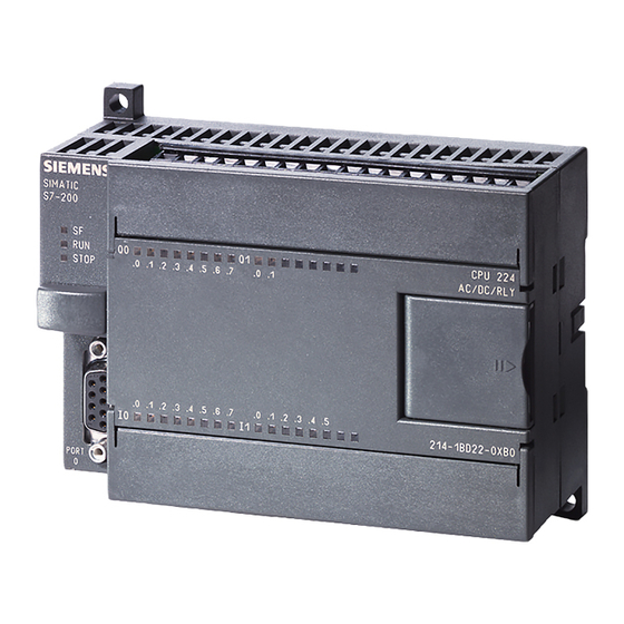
Siemens SIMATIC S7-200 Manual do sistema - Página 16
Procurar online ou descarregar pdf Manual do sistema para Equipamento industrial Siemens SIMATIC S7-200. Siemens SIMATIC S7-200 20 páginas. Ethernet gateway for simatic mpi/ profibus driver
Também para Siemens SIMATIC S7-200: Manual (30 páginas), Manual (35 páginas), Manual do condutor (28 páginas), Manual (49 páginas), Manual (18 páginas)

Table of contents
A.3.2
EM DT08, EM DR08, EM QR16, and EM QT16 digital output specifications ......................... 847
A.3.3
EM DT16, EM DR16, EM DT32, and EM DR32 digital input/output specifications................. 851
A.4
Analog inputs and outputs expansion modules (EMs) ....................................................... 857
A.4.1
EM AE04 and EM AE08 analog input specifications ........................................................... 857
A.4.2
EM AQ02 and EM AQ04 analog output module specifications ........................................... 860
A.4.3
EM AM03 and EM AM06 analog input/output module specifications ................................. 862
A.4.4
Step response of the analog inputs................................................................................... 866
A.4.5
Sample time and update times for the analog inputs ........................................................ 866
A.4.6
Measurement ranges of the analog inputs for voltage and current (SB and EM)................. 866
A.4.7
Measurement ranges of the analog outputs for voltage and current (SB and EM) .............. 868
A.5
Thermocouple and RTD expansion modules (EMs) ............................................................ 869
A.5.1
Thermocouple expansion modules (EMs) ......................................................................... 869
A.5.1.1
EM AT04 thermocouple specifications .............................................................................. 869
A.5.2
RTD expansion modules (EMs) ......................................................................................... 873
A.6
Digital signal boards......................................................................................................... 879
A.6.1
SB DT04 digital input/output specifications ....................................................................... 879
A.7
Analog signal boards........................................................................................................ 881
A.7.1
SB AE01 analog input specifications ................................................................................. 881
A.7.2
SB AQ01 analog output specifications............................................................................... 884
A.8
RS485/RS232 signal boards .............................................................................................. 885
A.8.1
SB RS485/RS232 specifications ......................................................................................... 885
A.9
Battery board signal boards (SBs) ..................................................................................... 887
A.9.1
SB BA01 Battery board ..................................................................................................... 887
A.10
EM DP01 PROFIBUS DP module......................................................................................... 889
A.10.1
S7-200 SMART CPUs that support the EM DP01 PROFIBUS DP module ............................... 890
A.10.2
Connector pin assignments for EM DP01 .......................................................................... 891
A.10.3
EM DP01 PROFIBUS DP module wiring diagram................................................................. 892
A.11
S7-200 SMART cables....................................................................................................... 892
A.11.1
S7-200 SMART I/O expansion cable .................................................................................. 892
A.11.2
RS-232/PPI Multi-Master Cable and USB/PPI Multi-Master Cable ......................................... 893
A.11.2.1
Overview ......................................................................................................................... 893
A.11.2.2
RS-232/PPI Multi-Master Cable.......................................................................................... 894
A.11.2.3
USB/PPI Multi-Master Cable .............................................................................................. 896
B
Calculating a power budget............................................................................................................... 899
B.1
Power budget .................................................................................................................. 899
B.2
Calculating a sample power requirement.......................................................................... 900
B.3
Calculating your power requirement ................................................................................ 901
C
Error codes ......................................................................................................................................... 903
C.1
Timestamp mismatch....................................................................................................... 903
C.2
PLC non-fatal error codes ................................................................................................. 904
C.3
PLC non-fatal error SM flags ............................................................................................. 906
C.4
PLC fatal error codes ........................................................................................................ 907
C.5
PROFINET alarm ............................................................................................................... 908
16
System Manual, V2.7, 08/2022, A5E03822230-AK
S7-200 SMART
