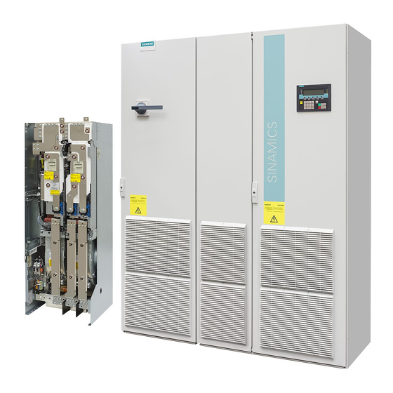
Siemens SINAMICS G130 Manual de Instruções - Página 11
Procurar online ou descarregar pdf Manual de Instruções para Equipamento industrial Siemens SINAMICS G130. Siemens SINAMICS G130 46 páginas. Line filter
Também para Siemens SINAMICS G130: Manual de Instruções (24 páginas), Manual de Instruções (26 páginas), Manual de Instruções (24 páginas), Manual de Instruções (31 páginas), Manual de Instruções (30 páginas), Manual de Instruções (28 páginas), Manual de Instruções (30 páginas), Manual de Instruções (22 páginas), Manual de Instruções (28 páginas), Manual de Instruções (30 páginas), Manual de Instruções (34 páginas), Manual de Instruções (46 páginas), Manual de Instruções (26 páginas), Manual de Instruções (26 páginas), Manual de Instruções (28 páginas), Manual de Instruções (42 páginas), Manual de Instruções (46 páginas), Manual de Instruções (24 páginas), Manual de Instruções (24 páginas), Manual de Instruções (30 páginas), Manual de Instruções (42 páginas), Manual de Instruções (38 páginas), Manual de Instruções (46 páginas), Manual de Instruções (28 páginas), Manual de Instruções (22 páginas), Manual de Instruções (24 páginas)

