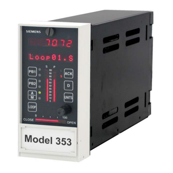
Siemens 353 Manual do utilizador - Página 14
Procurar online ou descarregar pdf Manual do utilizador para Controlador Siemens 353. Siemens 353 20 páginas. Multi-purpose training panel
Também para Siemens 353: Manual do utilizador (4 páginas)

Installation
2.5 CONTROLLER INSTALLATION
For installation details, refer to Figure 2-2 in this manual and to the Maintenance section of the Model 353 User's
Manual, Rev. 9 or higher.
1. Place a grounding wrist strap around your wrist and attach the ground wire clip to the GND receptacle at the
bottom right corner of Training Panel's front panel.
2.
If an Ethernet cable is installed in the case, dress the cable so that it lies on the floor of the case and centered
between the case sides.
3.
Remove the I/O Expander board from the static shielding bag. Insert Expander Board into the card guides on
the left side of the case, board components toward the center of the case. The Ethernet cable, if present, should
be to the right of the Expander board. Slide the board into the case until the card edge connectors on the board
meet the case-mounted connectors. Carefully apply additional force to seat the board.
4.
Remove the MPU Controller board from the static shielding bag. Install any needed option boards on the
Controller board; refer to the Assembly Replacement subsection in the Maintenance section of UM353-1.
Insert the Controller board into the right-side card guides, component side toward the center of the case. Slide
the board into the case until the card edge connectors on the board meet the case-mounted connectors. Carefully
apply additional force to seat the board.
5.
If an Ethernet option board is installed, mate the free end of the Ethernet cable with connector J4 on the
Ethernet board.
6.
Remove the Display Assembly from static shielding bag. Handle assembly by its bezel.
7.
Connect the MPU Controller board ribbon cable to the Display Assembly and close the locking levers. The
connectors are keyed.
8.
Position Display Assembly over the mouth of the case at the front of the Training Panel. Secure the Display
Assembly by tightening the two black captive screws.
9.
Detach the wrist strap ground clip from the case.
This completes the physical installation procedures for the Training Panel. Refer to the "Configuration Overview"
and "Function Block" sections of the User's Manual for configuration procedures.
2-4
UM353TP-1
April 2002
