Siemens TRI-D Instruções de instalação - Página 4
Procurar online ou descarregar pdf Instruções de instalação para Unidade de controlo Siemens TRI-D. Siemens TRI-D 4 páginas. Fire safety, addressable interface modules
NOTES (Cont.):
Ground shield wire ONLY at the specified location
on the Control Panel.
6.
If a Good Local Earth Ground is Available:
a. Terminal 5 must be connected to earth ground.
b. Use wire nuts to pass the shield wire through the
electrical box with NO connection to the device
terminal block or to local ground.
c. Use shielded wire to connect the switch wiring to the
TRI.
d. Tie the switch wiring shield to the ALD wiring shield.
Do not connect shield to terminal 5 or the local
earth ground.
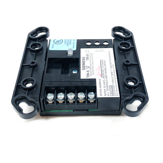
MOUNTING
Addressable Interface Models TRI-S, TRI-D, and TRI-R
mount directly into a (user supplied) double gang or 4
inch square electrical box. Fasten the module to the
square box with the switchplate using the 2 screws
provided.
NOTE: Be sure to program the TRI before fastening
the switchplate to the unit.
MOUNTING SLOTS
FOR 4 INCH SQUARE
ELECTRICAL BOX
MOUNTING SLOTS
FOR DOUBLEGANG
ELECTRICAL BOX
Mounting the TRI-S/-R/-D
P/N 315-096242-5
CAUTION
TRI-S/-D/-R
MODULE
MOUNTING
HOLES FOR
SWITCHPLATE
Figure 9
7.
If a Good Local Earth Ground is NOT Available:
Connect shield to terminal 5.
8.
If ALD wiring is not shielded, the switch wiring must
be in metal raceway.
9.
In supervisory:
TRI-S/-R draws 1.6mA
TRI-D draws 1.6mA
Terminal 5 of the TRI-S/-D/-R must be connected
to a known good earth ground for proper operation.
If the electrical box the TRI is installed in is
grounded, connect Terminal 5 to same.
IMPORTANT